- Shopping, made easy.
- /
- Get the app!
The 1-channel 12V relay module series uses patch optocouplers for isolation, with stable performance and user-friendly design. It can be triggered by high-level or low-level signals, and only requires 5mA current to drive a relay with a control capability of 30A. The module adopts power relays, small packaged optocouplers, high-power high-voltage transistors, red and green signal indicator lights, double-sided PCB boards, with comprehensive layout and stable performance. It is suitable for various single-chip microcontroller controls and can be widely used in various power control applications.
12V version
Static current: 5mA
Maximum current: 80mA
Trigger current: 2-4mA
Trigger voltage (low): 0-4V
Trigger voltage (high): 4.5-12V
Pin definition
1. DC+: Module DC power supply positive pole (trigger terminal voltage positive pole)
2. DC -: Module DC power supply negative pole (trigger terminal voltage negative pole)
3. IN: Signal trigger terminal (default trigger voltage is the same as the power supply)
4. JD+: Positive terminal voltage of relay control terminal
5. JD -: Negative terminal voltage of relay control terminal
6. Short circuit DC+and JD+with jumper caps, and short circuit DC - and JD - with jumper caps to trigger The voltage at the terminal is the same as that at the relay control terminal
7. Selection of high and low level triggering methods, as shown in the figure, when the jumper is connected to the L terminal, the IN terminal
Triggered at a low level, triggered at a high level when connected to the H terminal
8. Normally closed end (NC): Relay normally closed end
9. Common Terminal (COM): Relay Common Terminal
10. Constant start (NO): Relay constant start
 EC Buying 2Pcs LCUS-2 Type Dual-Channel Semiconductor Chip Housings 2-Channel USB Relay Module 5V Relay Module Onboard CH340 Microcontroller Chip USB Intelligent Control Switch Module
KWD 7.500
EC Buying 2Pcs LCUS-2 Type Dual-Channel Semiconductor Chip Housings 2-Channel USB Relay Module 5V Relay Module Onboard CH340 Microcontroller Chip USB Intelligent Control Switch Module
KWD 7.500
 EC Buying XH-M238 Power Module DC12V UPS Uninterrupted Power Supply Emergency Power Switching Power Outage Automatic Switching Battery Module
KWD 4
EC Buying XH-M238 Power Module DC12V UPS Uninterrupted Power Supply Emergency Power Switching Power Outage Automatic Switching Battery Module
KWD 4
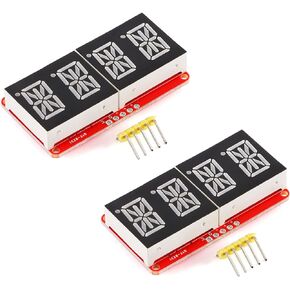 2Pcs 0.54" HT16K33 4 Bit Meter Digital Tube Module Emerald Green Color 0.54 inch LED Display Module I2C IIC for Arduino
KWD 5
2Pcs 0.54" HT16K33 4 Bit Meter Digital Tube Module Emerald Green Color 0.54 inch LED Display Module I2C IIC for Arduino
KWD 5
 EC Buying 5Pcs PCA9515A Dual Bidirectional I2C Bus SMBus Repeater Module CJMCU-9515 PCA9515A 400 KHz I2C Module I2C Buffer Board
KWD 6.500
EC Buying 5Pcs PCA9515A Dual Bidirectional I2C Bus SMBus Repeater Module CJMCU-9515 PCA9515A 400 KHz I2C Module I2C Buffer Board
KWD 6.500


