- Shopping, made easy.
- /
- Get the app!
Resistor Chip Arrays
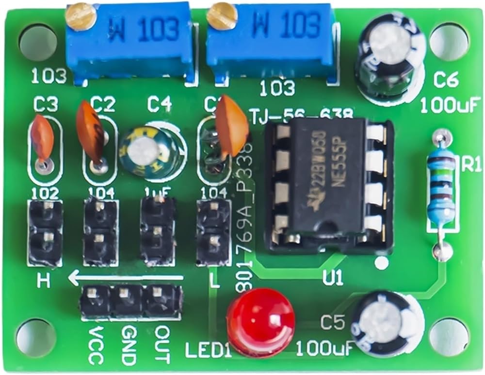
Product Name: NE555 Pulse Adjustable Generator Kit
Product model: TJ-56-638
Operating voltage: DC5~15V
PCB size: 38*29mm
Description:
This kit is used as a square-wave signal generator to generate square-wave signals for experimental development. Used to generate the square wave signal to drive the stepping motor driver; Generate adjustable pulses for MCU use; Generate adjustable pulses to control related circuits. Output with LED indication, optional output frequency range, fine tuning, output duty cycle can be adjusted.
Circuit diagram:
Circuit principle
The circuit consists of NE555 and its peripheral circuit. The power supply is input from 2 or 3 legs of J5, and C6 is the filter capacitance of the power supply. Resistors R2, R3 and jumper cap select the capacitor Cx to connect to form a timer circuit.
High level time: tPH_0.693* (R2+R3)*Cx
Low level time: tPL_0.693*R3*Cx
Oscillation period: T=tPH+tPL_0.693* (R2+2R3)*Cx
Oscillation frequency: =1/T_1/[0.693* (R2+2R3)*Cx]
Therefore, adjusting R2 and R3 potentiometers or choosing which capacitor to connect with using a jumper cap can change the frequency of the output pulse, and adjusting R2 and R3 can also change the duty cycle of the waveform. The pulse signal is output at 555's 3 feet. At low output level, D1 will light up, but not at high level. So the frequency of pulse can be obtained at low frequency through D1 flicker frequency. At high frequency, the flicker frequency is too fast. We can see it as a constant state from human eyes.
==========
Type : Voltage Regulator
Origin : Mainland China
 20PCS TM1650 TM1652 TM1616 TM2291 SMD SOP-16 Drive Digital Tube Chip(TM1616)
KWD 16
20PCS TM1650 TM1652 TM1616 TM2291 SMD SOP-16 Drive Digital Tube Chip(TM1616)
KWD 16
 20PCS 9926A ME9926A AP9926 SMD SOP-8 Low Voltage MOS Driver IC
KWD 15.500
20PCS 9926A ME9926A AP9926 SMD SOP-8 Low Voltage MOS Driver IC
KWD 15.500
 8PCS LD1117AV33 3.3V Transistor TO-220 LD1117 Low Dropout Regulator
KWD 16.500
8PCS LD1117AV33 3.3V Transistor TO-220 LD1117 Low Dropout Regulator
KWD 16.500
 5-10PCS AON7400A/7401/7409/7410/7544 SMD DFN3*3-8 N-Channel MOS FET(AON7544 5PCS)
KWD 15
5-10PCS AON7400A/7401/7409/7410/7544 SMD DFN3*3-8 N-Channel MOS FET(AON7544 5PCS)
KWD 15