- التسوق ، اصبح سهلا.
- /
- احصل على التطبيق!
In this circuit, quartz crystal oscillator is used as a time-based pulse oscillator, and second time-based signal is obtained after digital frequency division. The time is displayed through the counter, decoder and display. The crystal oscillator is used as the time base pulse, so the travel time is accurate.
Circuit installation and debugging:
Weld according to the sequence of the component list, and install the lower component first and then the higher component. The integrated circuit shall be installed on the pipe socket first, and then the integrated circuit shall be installed on the pipe socket finally.
Elements that do not distinguish the pin direction: resistor, crystal oscillator, ceramic chip capacitor, toggle switch.
Elements with positive and negative poles: the long legs of the LED and electrolytic capacitor are positive poles, facing the position marked with+on the circuit board, and the position with black circle of 1N4148 faces the position with white mark on the circuit board.
The notch position of the IC base is aligned with the direction of the notch position of the circuit board. Similarly, the notch position of the integrated circuit is aligned with the notch mark of the circuit board. The position that can be installed normally by touching the switch is correct.
Pin sequence recognition: the chip text is aligned with itself, and the first pin from the lower left corner is 1 counter clockwise.
 Feelyou Red Damask Wall Decor for Room Room Room Wall Art Antique Victorian Painting Wall Wallworks Hang Pictures for Office Decor
KWD 12
Feelyou Red Damask Wall Decor for Room Room Room Wall Art Antique Victorian Painting Wall Wallworks Hang Pictures for Office Decor
KWD 12
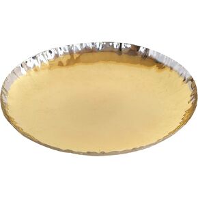 Dekulture المصنوعة يدويًا من النحاس النحاس النحاس المتجعد - صينية زخرفية ، لهجة الطاولة ، زفاف وعطلات (6.5 بوصة)
KWD 7
Dekulture المصنوعة يدويًا من النحاس النحاس النحاس المتجعد - صينية زخرفية ، لهجة الطاولة ، زفاف وعطلات (6.5 بوصة)
KWD 7
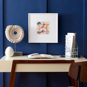 مجموعة Safavieh المنزلية عبر العديد من المحيطات Blush/Green Green 16 بوصة مربعة مربعة حديثة الجدار الإطار لغرفة النوم وغرفة المعيشة والهواة ومنطقة تناول الطعام ودخولها
KWD 11.500
مجموعة Safavieh المنزلية عبر العديد من المحيطات Blush/Green Green 16 بوصة مربعة مربعة حديثة الجدار الإطار لغرفة النوم وغرفة المعيشة والهواة ومنطقة تناول الطعام ودخولها
KWD 11.500
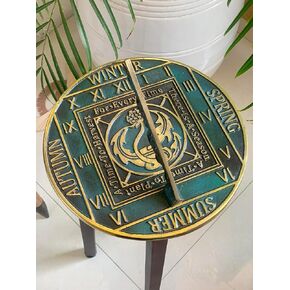 دورة موسم النحاس في حديقة Sundial ، المنزل والحديقة ديكور Vinatge الصلبة مع أبرز فيرديغريس - هدية عيد ميلاد ، هدية الزفاف ، هدية زوجين Sundial
KWD 36.500
دورة موسم النحاس في حديقة Sundial ، المنزل والحديقة ديكور Vinatge الصلبة مع أبرز فيرديغريس - هدية عيد ميلاد ، هدية الزفاف ، هدية زوجين Sundial
KWD 36.500


