- التسوق ، اصبح سهلا.
- /
- احصل على التطبيق!
Heaters
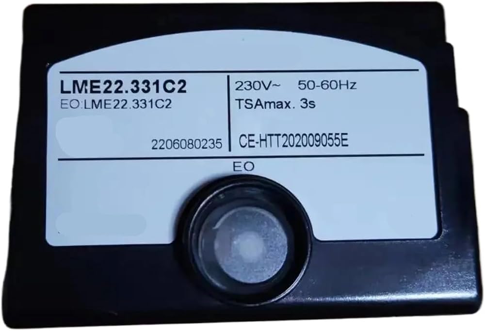
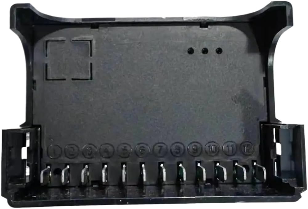
Pin 1: Ion detection signal line
Pin 2: Power supply Zero line
Pin 3: Power supply for ignition fan and also the common terminal for the wind pressure detection switch
Pin 6: Normally closed terminal of the wind pressure detection switch
Pin 11: Normally open terminal of the wind pressure detection switch
Pin 4: Power supply for the first-stage solenoid valve
Pin 5: Power supply for the second-stage solenoid valve
Pin 7: Power supply for the ignition
Pin 8: Reset signal
Pin 9: Only available in LME22 (power supply for the main burner air door purge actuator)
Pin 10: Fault output
Pin 12: Power supply Fire line
Additionally,Pin 1 is the ion detection signal line. If a UV probe is needed, an additional UV probe module AGQ3 is required to achieve it.
Startup sequence for LME21 controller:
After the start switch is closed (pins 2 and 12 receive power), the controller's yellow light turns on, and simultaneously pin 3 outputs a signal. The fan starts running, and during the purge time, the wind pressure switch is checked.
Pin 11 changes from normally open to normally closed, and pin 6 changes from normally closed to normally open.
If the wind pressure switch check is successful, the fan continues purging. After the purge time ends, the yellow light starts flashing. Pin 7 outputs a signal to activate the ignition , and simultaneously pin 4 outputs a signal to open the solenoid valve for ignition. Additionally, pin 1 is used for flame detection.
If no flame is detected within 3 seconds, the controller's red light turns on to indicate a fault
output.
If a flame is detected, the controller's light turns green, indicating successful ignition.
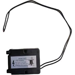 اشتعال الجهد نبض الشاعل 220 فولت ارتفاع ضغط الزيت الموقد الشاعل
KWD 33
اشتعال الجهد نبض الشاعل 220 فولت ارتفاع ضغط الزيت الموقد الشاعل
KWD 33
 قرص مثبت اللهب الهوائي | حلقة تثبيت لرذاذ حرق نفايات الزيوت والنار
KWD 18.500
قرص مثبت اللهب الهوائي | حلقة تثبيت لرذاذ حرق نفايات الزيوت والنار
KWD 18.500
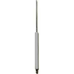 سلك التحكم قضيب السيراميك الإشعال قضيب القطب لهب ردع التحقيق التحقيق طويل حرق عصا الموقد الملحقات أيون التحقيق (12X125mm)
KWD 25.500
سلك التحكم قضيب السيراميك الإشعال قضيب القطب لهب ردع التحقيق التحقيق طويل حرق عصا الموقد الملحقات أيون التحقيق (12X125mm)
KWD 25.500
 IFD258-3/1W جهاز التحكم بالإشعال (IFD258-10 1W)
KWD 451
IFD258-3/1W جهاز التحكم بالإشعال (IFD258-10 1W)
KWD 451