- التسوق ، اصبح سهلا.
- /
- احصل على التطبيق!
Basic Information
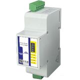
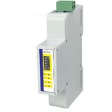
Model: Main Meter ME131M / Sub-Meter ME131S
Installation Method: DIN Rail
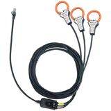
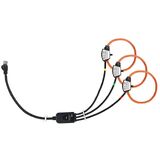
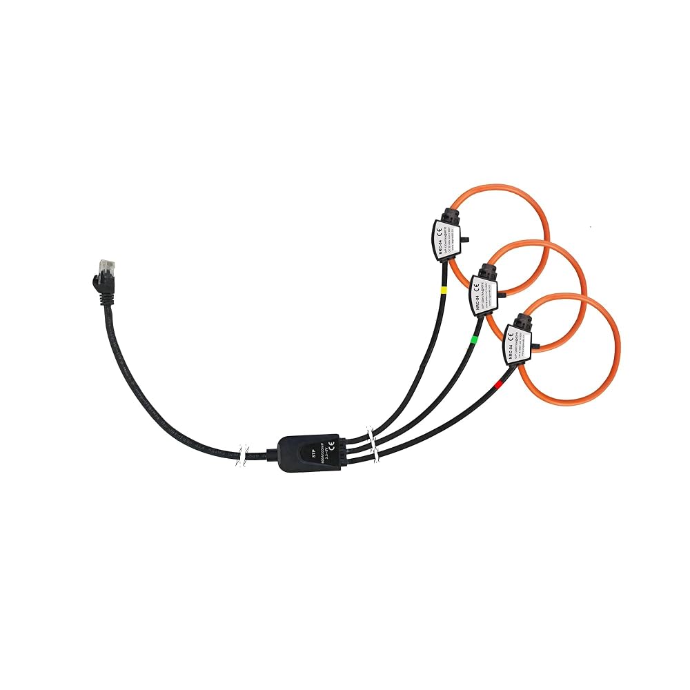
Current Sensor: Rogowski Coil, Voltage Output Current Transformer
Core Features: Direct Rogowski Coil Connection Available, Supports Wireless Measurement, Wide Current Range
Wiring System: 3P4W_3CT, 3P3W_3CT, 3P3W_2CT, 1P3W, 1P2W
Application Scenarios: Power Analysis, Energy Consumption Monitoring
Display: None
Weight: ME131M: 122g / ME131S: 59g
Dimensions: ME131M: 9.3×8.0×3.6cm / ME131S: 9.3×8.0×1.81cm
Electrical and Communication Parameters
Table
Item Specifications
Channel Input Voltage 0-900mVAC peak, 636mV RMS
Rogowski Coil Range 50mV/kA@50Hz (0-12000A), 85mV/kA@50Hz (0-7000A), 100mV/kA@50Hz (0-6000A)
Voltage Measurement Range: 0~600VAC
Relay Output: 1-channel electromagnetic relay output, contact capacity: 3A 30V DC / 3A 250V AC
RS485 Communication: Two-wire half-duplex, baud rate 2400~38400bps, Modbus-RTU protocol
Power Supply: 85-265VAC/110-370VDC, 45-60Hz (24V DC power supply can be customized)
Maximum Power Consumption: ≤3.5VA
Measurement Parameters: Instantaneous Values: Phase Voltage / Line Voltage / Zero Sequence Voltage, Current / Zero Sequence Current, Grid Frequency, Power Factor, Fundamental Power Factor, Active / Reactive / Apparent Power (Phase and Total)
Electrical Energy: Positive/Negative Active Energy, Positive/Negative Reactive Energy, Apparent Energy, Time-of-Use Energy (ET1-ET6)
Harmonics: Voltage/Current Harmonic Distortion Rate (Total/Odd/Even/1-50th Harmonics), Harmonic Value, Current K-coefficient
Phase and Imbalance: Phase Sequence, Voltage/Current Phase Angle, Voltage/Current Phase Difference; Voltage/Current Imbalance (Negative Sequence/Zero Sequence Components)
Extrema and Demand: Maximum/Minimum Values of Voltage/Current/Power in Each Phase; Maximum Demand and Time for Total Active/Reactive/Apparent Power
 محلل جودة الطاقة، فئة حماية IP20، درجة حرارة التشغيل -25 درجة مئوية إلى +70 درجة مئوية -MC-61 مقياس ذكي متعدد الدوائر
KWD 197.500
محلل جودة الطاقة، فئة حماية IP20، درجة حرارة التشغيل -25 درجة مئوية إلى +70 درجة مئوية -MC-61 مقياس ذكي متعدد الدوائر
KWD 197.500
 محلل جودة الطاقة، ME435 جهاز قياس ملف محلل الطاقة ثلاثي الطور المحمول Rogowski(ME435+NRC150)
KWD 371
محلل جودة الطاقة، ME435 جهاز قياس ملف محلل الطاقة ثلاثي الطور المحمول Rogowski(ME435+NRC150)
KWD 371
 محلل جودة الطاقة، مشبك الجهد CC03
KWD 42
محلل جودة الطاقة، مشبك الجهد CC03
KWD 42
 محلل جودة الطاقة، مسجل شكل موجة البرق الذكي LD300، مستشعر، تيار الذروة، عدد الضربات
KWD 513
محلل جودة الطاقة، مسجل شكل موجة البرق الذكي LD300، مستشعر، تيار الذروة، عدد الضربات
KWD 513