- التسوق ، اصبح سهلا.
- /
- احصل على التطبيق!
Item Details
1.Product description
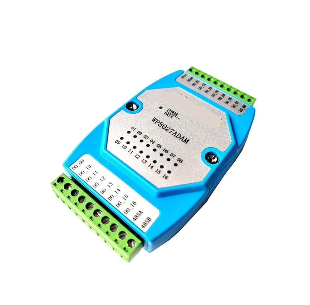
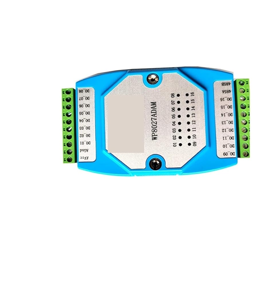
16ch optoelectronic isolation digital output(NPN)
Using RS485 MODBUS RTU communication standard. It can be netted with configuration software, PLC and industry touch pad
Communication, input and output status LED
Communication circuit designed for lightening protection and interference immunity
Could be used for signal collection and control of Industrial field apparatus
3 Year's for normal use
2.Specification
Digital output channel 16ch (NPN output,500mA)
Working Temperature -20-70°C
External power supply DC 9V-30V/2W
Isolation protect 1500VDC
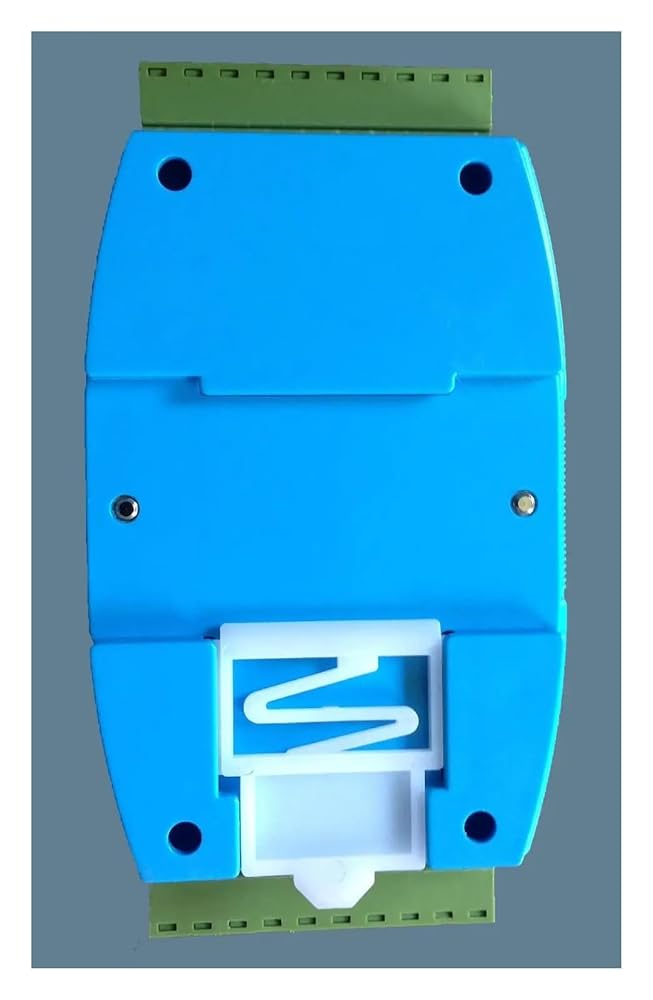
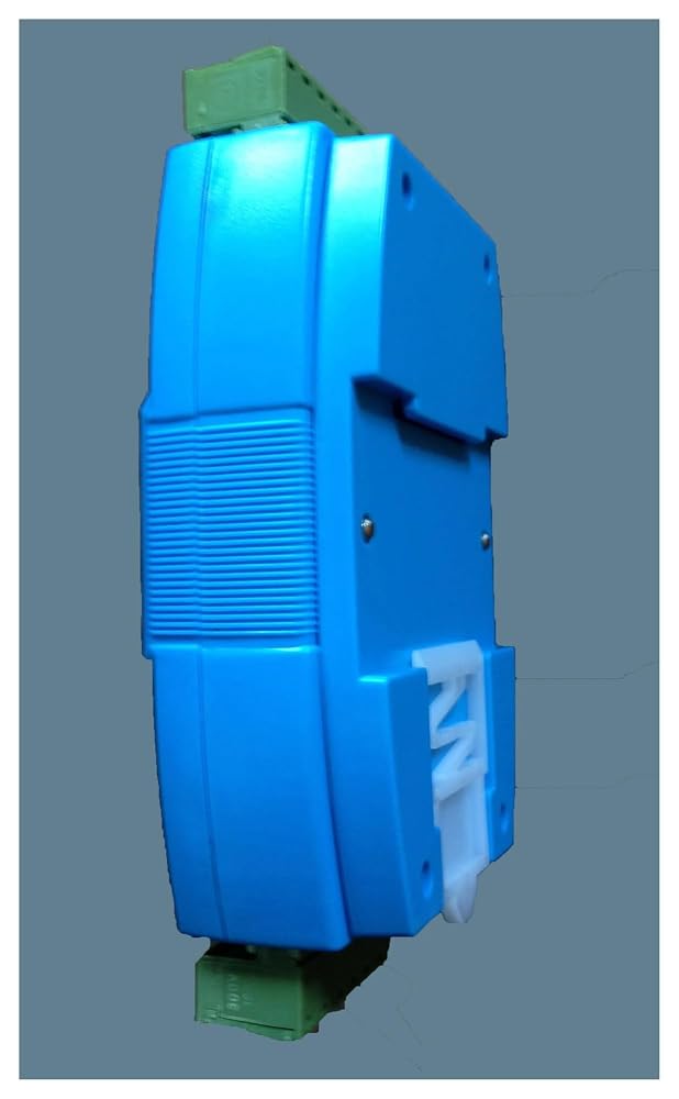
Installation method Standard DIN slide rail or screw
Dimension 125×73×35mm
3.Interface definition
AVcc
External PSU positive terminal input
AGnd
External PSU negative terminal input
DO_01
Digital output in 1stch
DO_02
Digital output in 2ndch
DO_03
Digital output in 3rdch
DO_04
Digital output in 4thch
DO_05
Digital output in 5thch
DO_06
Digital output in 6thch
DO_07
Digital output in 7thch
DO_08
Digital output in 8thch
DO_09
Digital output in 9stch
DO_10
Digital output in 10ndch
DO_11
Digital output in 11rdch
DO_12
Digital output in 12thch
DO_13
Digital output in 13thch
DO_14
Digital output in 14thch
DO_15
Digital output in 15thch
DO_16
Digital output in 16thch
485A
RS485 signal A+
485B
RS485 signal B-
4 Digital output application diagram
5 Communication Instruction
5.1 Communication parameter (default setting): 9600,N,8,1
Parameter
Description
9600
baud rate
N(no check)
check bit
8 data bit
1 stop bit
5.2 Command for digital output (several controls):
Send: 01 0F 00 00 00 10 02 21 86 7B D2 (example/hexadecimal)
data
byte
data description
remark
01
1 module address
address range 01-FE
0F
1 function code
0F-write multiple coil
0000
2 coil address
(0x mode)
0000-initial address of coil
0010
2 write coil length
0010-write 16 coils
02
1 write data byte
02-write 2 byte data
2186
2 write data
2186-write 16 coil's output status
7BD2
2 check code
check code for all data
Receive: 01 0F 00 00 00 08 54 0D (example/hexadecimal)
Converting input data "21" to 2 hexadecimal results "0010 0001". From left to right, it represent the 8 relay output status DO_08-DO_01.Converting input data "86" to 2 hexadecimal results "1000 0110". From left to right, it represent the 8 relay output status DO_16-DO_09.Here it means DO_16,DO_11,DO_10,DO_06,DO_01 has output but others no.Module will take corresponding action after receiving correct command and send the response back to master. It means successful communication.
5.3 Command for digital output (single control):
Send: 01 05 00 00 FF 00 8C 3A (example/hexadecimal)
Receive: 01 05 00 00 FF 00 8C 3A (example/hexadecimal)
When module receives correct command, it will make corresponding actions and send response back to the master. This is successful communication.
5.4 Command for state collection of digital output:
Send: 01 01 00 00 00 10 3D C6 (example/hexadecimal)
data
byte
data description
remark
01
1 module address
address range 01-FE
01
1 function code
01-read coil status
0000
2 oil address
(0x mode)
0000-initial address of coil
0010
2 read coil length
0010-read 16 coil status
3DC6
2 check code
check code for all data
Receive: 01 01 02 21 86 20 0E (example/hexadecimal)
data
byte
data description
remark
01
1 module address
address range 01-FE
01
1 function code
01-read coil status
02
1 byte number
02-read 2 byte length
2186
2 read data
2186-read coil status
200E
2 check code
check code for all data
Converting input data "21" to 2 hexadecimal results "0010 0001". From left to right, it represent the 8 digital output status DO_08-DO_01. Converting input data "86" to 2 hexadecimal results "1000 0110". From left to right, it represent the 8 digital output status DO_16-DO_09.Here it means DO_16,DO_11,DO_10,DO_06,DO_01 has output but others no.
5.5 command for module address setting:
Send:00 06 00 64 00 01 08 04 (example/hexadecimal)
date
byte
data description
remark
00
1 module address
00-group sending
06
1 function code
06-write single register
0064
2 register address
(4x mode)
0064-modify module address
0001
2 data writing
set address for module, range 0001-00FE
0804
Send:01 06 00 65 00 02 18 14 (example/hexadecimal)
Receive:01 06 00 65 00 02 18 14 (example/hexadecimal)
This command means to send a code to the module and set the communication parameter as "9600, N (No check), 8, 1".This setting could be saved when power off. The default communication parameter is "9600, N (no check), 8, 1". Attention is required, when electing the correct communication parameter in communication setting and restarting the communication terminal, setting will be done.Normally, the lower of baud rate, the lower of the transaction speed but the higher of transaction stability. The opposite is also true.When module receives correct command, corresponding action will be taken and response will be sent back to the master. This is successful communication.
6.Indicator LED description
When module powered on, Led is green.
When module is under communication, LED is twinkling.
when module receive correct command, LED is green.
when module receive incorrect command or command for other modules, LED is red.
7.PC debugging instruction
This module provides software for parameter setting and function test. Please follow the steps below:
Origin : Mainland China
Certification : CE
 محور عازل USB 4CH من الدرجة الصناعية، وحدة واحدة إلى أربع وحدات مع غلاف مضاد للتدخل ومضاد للكهرباء الساكنة
KWD 0
محور عازل USB 4CH من الدرجة الصناعية، وحدة واحدة إلى أربع وحدات مع غلاف مضاد للتدخل ومضاد للكهرباء الساكنة
KWD 0
 485 مكرر محور العزلة الكهروضوئية الصناعية 4 قناة RS485 جامع موزع مقسم 1 في 4 خارج
KWD 22.500
485 مكرر محور العزلة الكهروضوئية الصناعية 4 قناة RS485 جامع موزع مقسم 1 في 4 خارج
KWD 22.500
 IDM-3182-FC1 المنفذ التسلسلي حلقة شبكة جهاز الإرسال والاستقبال البصري RS485 الألياف البصرية محول الشفاء الذاتي جهاز الإرسال والاستقبال RS232
KWD 63
IDM-3182-FC1 المنفذ التسلسلي حلقة شبكة جهاز الإرسال والاستقبال البصري RS485 الألياف البصرية محول الشفاء الذاتي جهاز الإرسال والاستقبال RS232
KWD 63
 ADM-3142 2CH RS485 إلى جهاز إرسال واستقبال الألياف البصرية ثنائي الاتجاه جهاز الإرسال والاستقبال البصري الصناعي 24 فولت منفذ SC التسلسلي للسكك الحديدية
KWD 0
ADM-3142 2CH RS485 إلى جهاز إرسال واستقبال الألياف البصرية ثنائي الاتجاه جهاز الإرسال والاستقبال البصري الصناعي 24 فولت منفذ SC التسلسلي للسكك الحديدية
KWD 0