- Shopping, made easy.
- /
- Get the app!
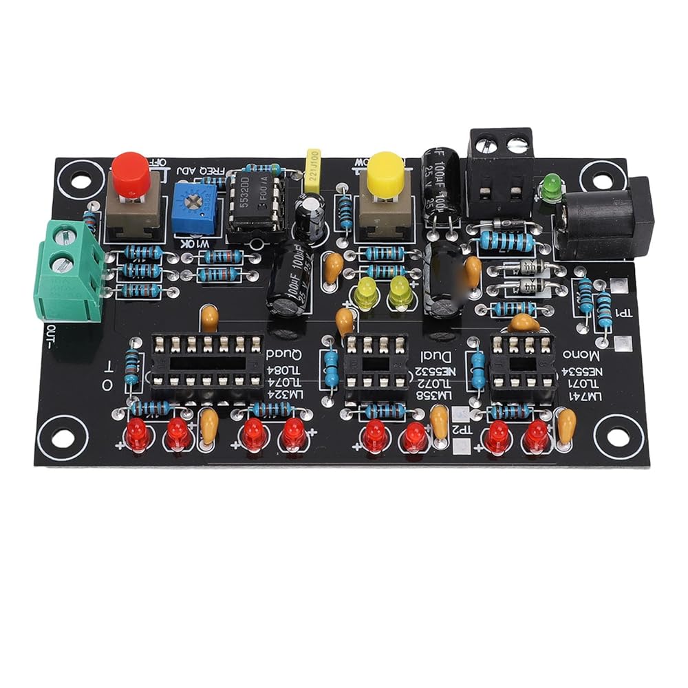
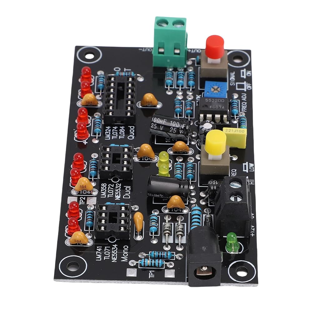
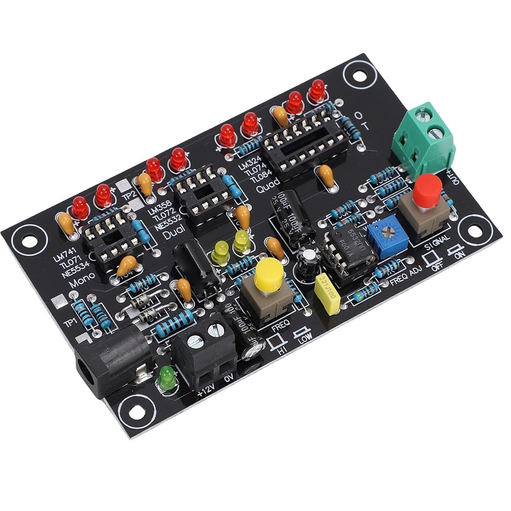
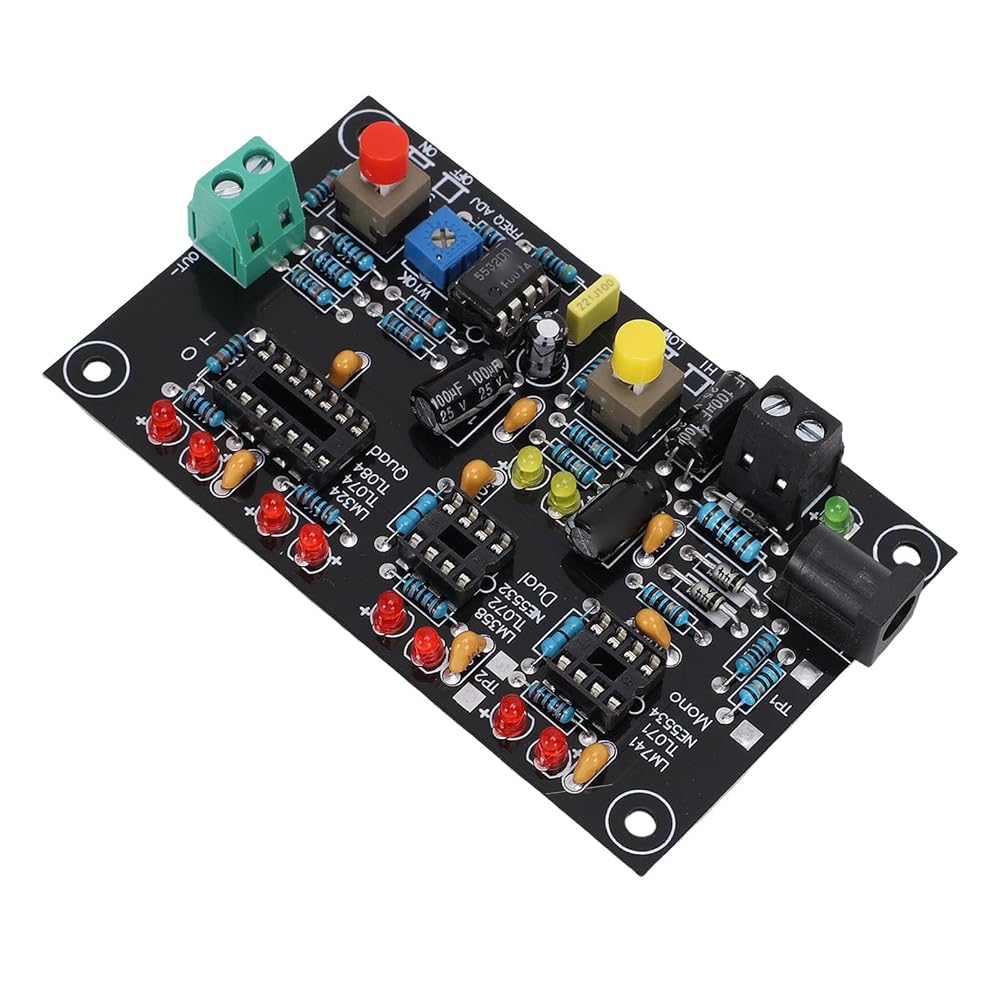
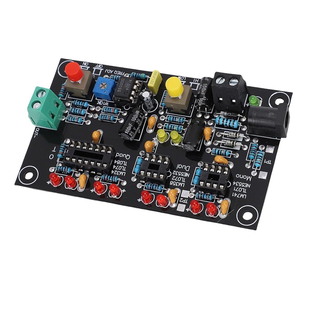
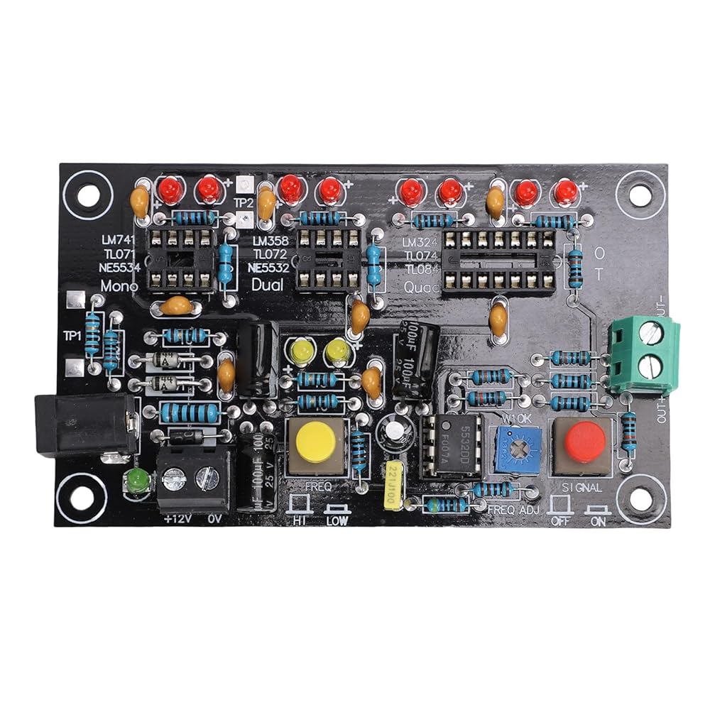
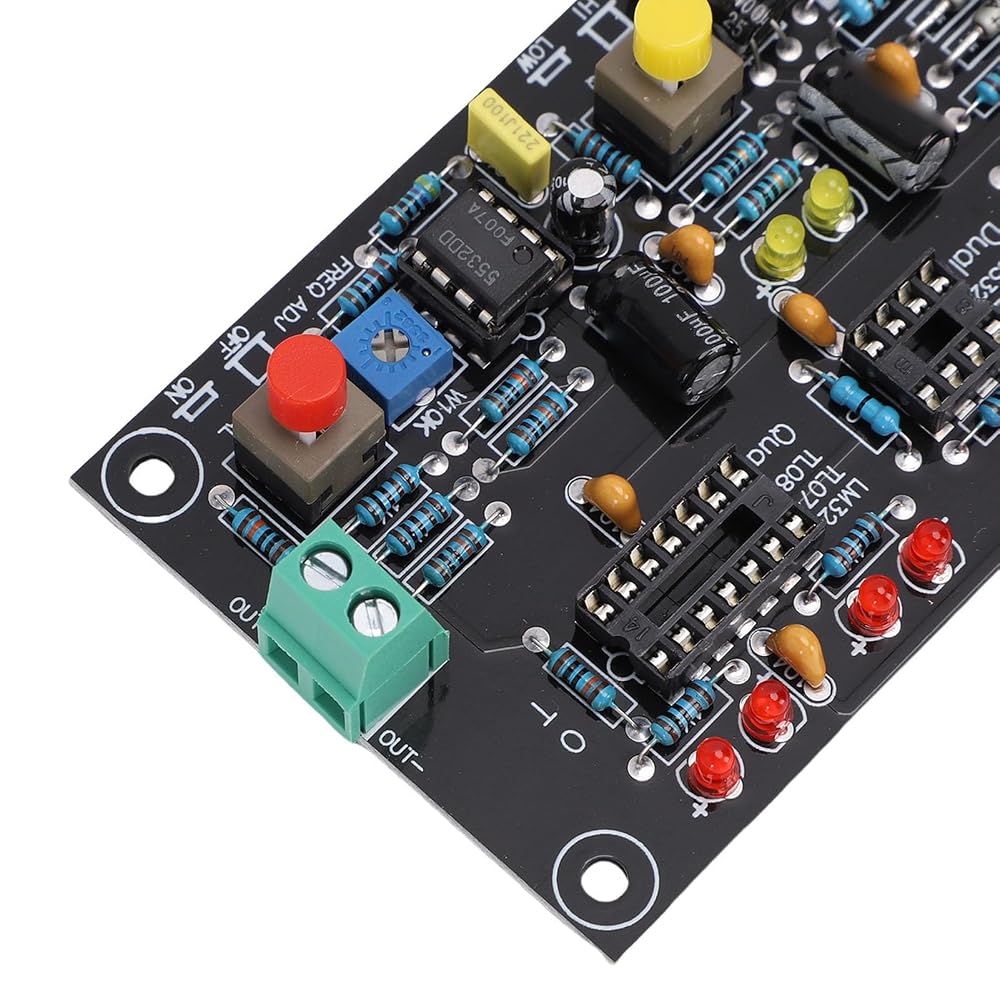
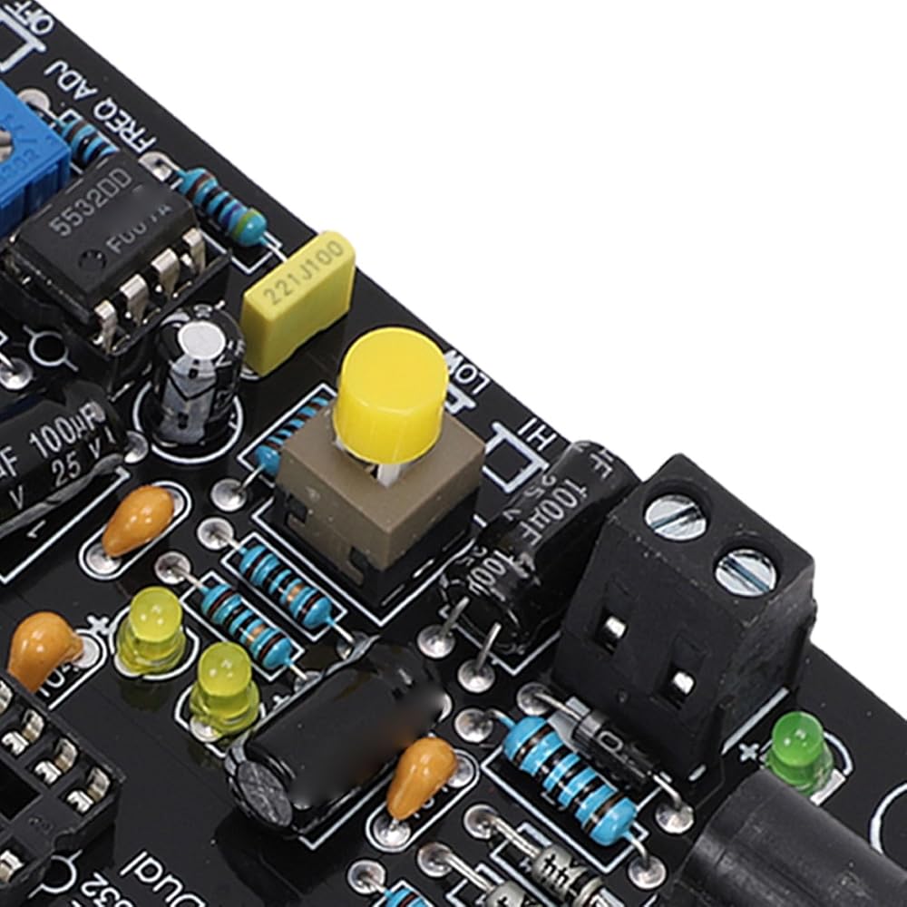
1. [COMPREHENSIVE CHIP TESTING] The T2 upgrade OP AMP testing board accurately tests single, double, and quad OP AMPs, measuring conversion rates, static current, and DC offset to ensure the IC's suitability for amplification.
2. [HIGH SPEED OUTPUT] Test high speed OP AMPs effortlessly with clear distinctions between high and low speed chips, with red and green LEDs indicating output at different frequencies.
3. [ FUNCTIONALITY] Equipped with test terminals for static current testing and output display for low speed OP AMPs, allowing for easy identification and differentiation between .
4. [EASY CURRENT TESTING] Test the static current of OP AMPs under +/- 5V power supply to understand amplifier characteristics and distinguish between different .
5. [VERSATILE APPLICATION] Compatible with common OP AMP for single, double, and quad configurations, including popular options like LM741, LM358, and LM324.
Specification:
Item Type: Operational Amplifier Testing Module Board
Material: PCB
Size: Approx. 9.5x5.8cm / 3.74x2.28in
Power Supply Requirements(2 modes, you can choose one of them according to the actual situation):
1. Wiring Method: Current: Above 100mA
2. Use A Regular Monitoring Power Supply: 1A power adapter, plug approx. 5.5 x 2.5mm / 0.22 x 0.1in
, positive inside and negative outside.
Application:
For Single OP AMP Model: LM741, LF356, NE5534, TL071, TL081, 0P07 and other standard single OP AMP packages
For Double OP AMP Model: LM358, NE5532, TL072, TL082, MC1458, 0P275, and other standard double OP AMP packages
For Quad OP AMP Model: LM324, TL074, TL084, LF347, AD713
How to Use:
Direct installation and use
PackageList:
1 x Operational Amplifier Testing Module Board
Note:
Testing Instructions:1. Only test one chip at a time. Use one of the three test sockets.
2. For static current testing, use the DC voltage meter of the digital multimeter. Test the voltage across 10 ohms, 1=V/10 (ma). For example, V=15MV, static current 1=1.5 ma. (at this time, do not press the red switch on the right side of the diagram).
3. The test end can be connected to an oscilloscope or frequency counter. Adjust the potentiometer to change the test frequency.
 Digital Clamp Meter Multimeter, 5 Count Auto Ranging Amp Tester, Multimeter Voltage Tester with Backlit Display Screen, AC and DC Current, AC Voltage, Resistor, Capacitance Test
KWD 8.500
Digital Clamp Meter Multimeter, 5 Count Auto Ranging Amp Tester, Multimeter Voltage Tester with Backlit Display Screen, AC and DC Current, AC Voltage, Resistor, Capacitance Test
KWD 8.500
 -15%
Computer Graphics Card Tester with Light, Video Graphics Card Tester, High Accuracy, Quick Fault Diagnosis Tool for Graphics CPU Chip
KWD 16.500
-15%
Computer Graphics Card Tester with Light, Video Graphics Card Tester, High Accuracy, Quick Fault Diagnosis Tool for Graphics CPU Chip
KWD 16.500
 CAN Analyzer Module, 170MHz USB to CAN Module Type C Power Supply Converter Adapter, CAN Bus Module Transceiver, for CAN 2.0A, CAN 2.0B, and CAN FD
KWD 13.500
CAN Analyzer Module, 170MHz USB to CAN Module Type C Power Supply Converter Adapter, CAN Bus Module Transceiver, for CAN 2.0A, CAN 2.0B, and CAN FD
KWD 13.500
 LICAEVEY Body Camera with Audio and Video Recording, 1080P HD Wearable Camcorder with Night Vision & Stabilization, for Security Work, Travel, Vlogging
KWD 14.500
LICAEVEY Body Camera with Audio and Video Recording, 1080P HD Wearable Camcorder with Night Vision & Stabilization, for Security Work, Travel, Vlogging
KWD 14.500