- التسوق ، اصبح سهلا.
- /
- احصل على التطبيق!
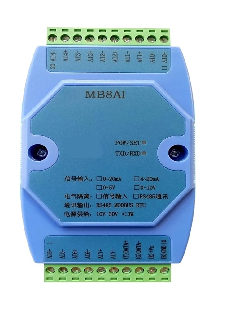
MB8AI 8 analog input module, which can gather 8 road 0~20mA, 4~20mA, 0~5V and 0~10V four kinds of signals, each channel can customize the input analog signal collected data, through the RS485 interface output module, using Modbus-RTU communication, can be directly adapted PLC, DCS and a variety of configuration software in china. Signal acquisition, power supply, RS485 communication electrical signals isolated from each other
default input type: 4-20mA (4-20mA,0-5V,0-10V,0-20mA)
The first chapter product introduction
A.Summary
MB8AI 8Analog acquisition module, which can gather 8 road 0~20mA, 4~20mA, 0~5Vand 0~10Vfour kinds of analog signal, analog signal collected data, by isolating the RS485 interface output module based on Modbus-RTU communication, can be directly adapted PLC, DCS and various configuration software.
Signal acquisition, power supply, RS485 communication electrical signal isolation, the effective suppression of all kinds of serial mode and common mode interference, to ensure the accuracy of the data, but also to ensure the reliability of the module.
Two.Characteristic
1.Using Modbus-RTU protocol.
2.According to their own needs to set the input signal type of each channel.
3.Signal acquisition, power supply, RS485 communication electrical signals isolated from each other.
4.RS485The communication signal output interface is protected by the overvoltage and overcurrent.
5.Input signal type and communication format can be set by software.
SixPower polarity protection.
Three.Technical index
project
parameter
Signal input
1Input channel: 8 channel isolation acquisition
2Signal type: 0~20mA, 4~20mA, 0~5V and 0~10V four analog signal
3Sampling rate:200HZ(each channel per secondTwenty-fiveTimes)
4Resolution: 12 bit AD
FiveAcquisition accuracy:Voltage input0.2%Current input0.3%
SixADAcquisition circuit and CPUIsolated voltage protection: 1500V
Communication output
1Communication protocol: MODBUS-RTU
2Interface type: isolated RS485 communication, the output of the interface using the overvoltage and overcurrent protection
3Baud rate: 1200BPS, 2400bps., 4800bps, 9600bps, 19200bps
4Check bit: no parity check, parity check
5. setting: module address, baud rate, parity bits can be set by software
6Communication distance: 9600bps 1200 meters
7 RS485 communication circuitCircuit and CPUIsolated voltage protection: 1500V
Module size
A.Separate module size: 104mm*72mm*26mm
B.With terminal and guide rail box size: 124mm*72mm*45mm
Installation method
standardDINDIN-Rail Mounting(35mmGuide rail or high or low)
work environment
Temperature: -10 ~ +55 temperature humidity: 35~85% (not dew)
Working power supply
1Power supply voltage: 10V~30V wide range of power supply, with the power supply polarity protection
2Power consumption: less than 3W
Four.Product appearance
Five.Function description of module indicator
1.POW/SET;Module working status indication
A.The traffic lights are always on: the module works in the running state B. red light is always bright: the module is working in the configuration mode
2.TXD/RXD:Communication status indication
A.The green light flashes: the communication receives the data B. red light flashes: the module is sending data
C.The green light is always on: DATA+ and DATA- on the communication line RS485 line is connected to the reverse or the connection is broken.
Six.Module on the right side of the switch function description
1.Working mode: switch to the top, and then re power module power supply module; use this mode when in normal work, this model cannot be configured to work parameters; communication parameter mode is the parameter set by the user, the default communication parameters (address: 1, Potter rate: 9600bps: No, stop bit parity bit 1).
2.Configuration mode: switch to the following, and then re power for power module; communication parameter setting module, view or analog input and analog output parameters, communication parameter mode is fixed (address: 1, baud rate: 9600bps, parity: No, stop bit: 1).
Seven.Terminal definition
terminal
Name
Explain
terminal
Name
Explain
1 IN5+
Analog input 5 channel positive end
11
IN0+
Analog input 0 channel positive end
2 IN5-
Analog input 5 channel negative terminal
12
IN0-
Analog input 0 channel negative terminal
3 IN6+
Analog input 6 channel positive end
13
IN1+
Analog input 1 channel positive end
4 IN6-
Analog input 6 channel negative terminal
14
IN1-
Analog input 1 channel negative terminal
5 IN7+
Analog input 7 channel positive end
15
IN2+
Analog input 2 channel positive end
6 IN7-
Analog input 7 channel negative terminal
16
IN2-
Analog input 2 channel negative terminal
7 DATA+
RS485Communication +
17
IN3+
Analog input 3 channel positive end
8 DATA-
RS485Communication -
18
IN3-
Analog input 3 channel negative terminal
9 +Vs
Power input +
19
IN4+
Analog input 4 channel positive end
10
GND
Power input -
20
IN4-
Analog input 4 channel negative terminal
Eight.Power supply and communication connection
The second chapterModbusRegister and communication protocol
A.Module supports MODBUS function code and address range
Register type
Address range
Function code
Functional code description
Input register
30001-30008
0x04H
Read one or more input registers
Hold register
40033-40040
40065-40076
40129-40136
0x03H
Read one or more hold registers
0x06H
Write a data to hold register
0x10H
Write one or more data to hold register
Certification : CE
 485 مكرر العزلة الكهروضوئية الصناعية الصف RS485 محور 2 ميناء مكبر صوت أحادي مكافحة التشويش الحماية
KWD 19.500
485 مكرر العزلة الكهروضوئية الصناعية الصف RS485 محور 2 ميناء مكبر صوت أحادي مكافحة التشويش الحماية
KWD 19.500
 جهاز تحكم وحدة تحكم شبكة إيثرنت IP الصناعية ذات 8 قنوات إيثرنت إلى RS485 مرحل ثنائي الاستقرار MODBUS
KWD 54.500
جهاز تحكم وحدة تحكم شبكة إيثرنت IP الصناعية ذات 8 قنوات إيثرنت إلى RS485 مرحل ثنائي الاستقرار MODBUS
KWD 54.500
 1 في 2 خارج تيار مستمر/تيار مستمر إشارة عزل الموزع المعزل 4-20mA 0-10 فولت الجهد الحالي محول التناظرية 24VDC وحدة DIN السكك الحديدية
KWD 33.500
1 في 2 خارج تيار مستمر/تيار مستمر إشارة عزل الموزع المعزل 4-20mA 0-10 فولت الجهد الحالي محول التناظرية 24VDC وحدة DIN السكك الحديدية
KWD 33.500
 مفتاح إيثرنت من الدرجة الصناعية 5 منافذ 8 منافذ مفتاح صناعي 12V24V دليل التبديل IDM-7180 IDM-7150
KWD 35
مفتاح إيثرنت من الدرجة الصناعية 5 منافذ 8 منافذ مفتاح صناعي 12V24V دليل التبديل IDM-7180 IDM-7150
KWD 35

 الكويت