- التسوق ، اصبح سهلا.
- /
- احصل على التطبيق!
Key Specifications
Input Voltage: 5V via USB (Bus-Powered)
Logic Voltage: 3.3V or 5V (Auto-Detect Compatible)
Baud Rate: 300 bps to 1 Mbps (TTL/RS232 Supported)
Data Buffers: 512-byte TX/RX FIFO (Prevents Data Loss)
Data Format: 5-8 Data Bits, 1/1.5/2 Stop Bits, Odd/Even/Mark/Space/None Parity
OS Support: Windows XP-11, macOS 10.4+, Linux 2.6+, Android
Protections: Self-Recovery Fuse (Short-Circuit Protection)
LED Indicators: Power (Red), TX (Green), RX (Yellow) - Dims at High Baud Rates
Pin Functions
VCC: Power Output (3.3V or 5V). Critical: Match target device voltage!
GND: Common ground for power/logic signals (Star Grounding Recommended)
TXD: UART Transmit → Connect to MCU.RXD (Data Flow: PC → Target Device)
RXD: UART Receive ← Connect to MCU.TXD (Data Flow: Target Device → PC)
DTR: Data Terminal Ready (Auto-Reset Signal for Arduino/STM32 Programming)
5V/3V3 Jumper: Select output voltage (Default: 5V)
Logic Warning: TTL uses +5V="1"/0V="0" (Positive Logic). RS232 uses -12V~3V="0"/+3V~12V="1" (Negative Logic).
FAQ
Q1: Driver fails on Windows 11?
Install latest VCP driver from Silicon Labs. Temporarily disable driver signature enforcement if blocked by OS security.
Q2: No serial communication?
① Verify TXD→MCU.RXD and RXD→MCU.TXD (Cross-Wired!); ② Check voltage jumper matches MCU; ③ Perform loopback test: Short TXD-RXD to confirm self-transmission capability.
Q3: 5V output damages 3.3V device?
Critical: Set VCC jumper to 3.3V when connecting to ESP32/Raspberry Pi. 5V logic destroys 3.3V ICs!
 -23%
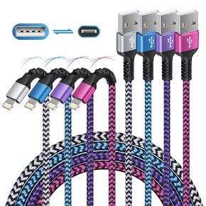
iPhone Charger 4Pack/3-6ft ، كابلات Lightning Long Lwired ، سلك شاحن الطاقة الشحن السريع لـ iPhone 14 13 12 Pro Max/11pro Max/Se/X/XS/XR/8/7 Plus ، iPad Mini ، Air ، Cargador Wire Colored Colored
KWD 5
-23%
iPhone Charger 4Pack/3-6ft ، كابلات Lightning Long Lwired ، سلك شاحن الطاقة الشحن السريع لـ iPhone 14 13 12 Pro Max/11pro Max/Se/X/XS/XR/8/7 Plus ، iPad Mini ، Air ، Cargador Wire Colored Colored
KWD 5
 -8%
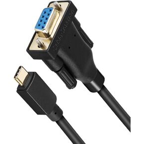
Cablecreation USB-C إلى RS232 محول تسلسلي مع رقاقة PL2303 10 أقدام ، RS232 DB9 محول أنثى Cable Thunderbolt 3 منفذ متوافق مع MacBook Pro ، IMAC ، XPS 13 ، XPS 15 ، Surface Pro ، 3M Black
KWD 5.500
-8%
Cablecreation USB-C إلى RS232 محول تسلسلي مع رقاقة PL2303 10 أقدام ، RS232 DB9 محول أنثى Cable Thunderbolt 3 منفذ متوافق مع MacBook Pro ، IMAC ، XPS 13 ، XPS 15 ، Surface Pro ، 3M Black
KWD 5.500
 TRIPP LITE 18IN CABLE INTERNAL SAS
KWD 8.500
TRIPP LITE 18IN CABLE INTERNAL SAS
KWD 8.500
 Boenoea USB C Cable 10 ft ، 4 عبوات USB A إلى USB C كبل الشحن السريع النوع C سلك الشاحن مضفر لـ Samsung Galaxy S24 S23 S22 S20 S20 S10E Note 20 10 A50 A51 A71 Moto G ، Pixel
KWD 4
Boenoea USB C Cable 10 ft ، 4 عبوات USB A إلى USB C كبل الشحن السريع النوع C سلك الشاحن مضفر لـ Samsung Galaxy S24 S23 S22 S20 S20 S10E Note 20 10 A50 A51 A71 Moto G ، Pixel
KWD 4


