- التسوق ، اصبح سهلا.
- /
- احصل على التطبيق!
Key Parameters
Interface Type: I²C serial communication (supports 100kHz/400kHz/1.7MHz modes).
I/O Quantity: 16 bidirectional GPIO pins (PORTA: 8-bit, PORTB: 8-bit), independently configurable as input/output.
Drive Capability: 25mA sink/source per pin (directly drives LEDs, relays, etc.).
Operating Voltage: 1.8V–5.5V DC (Reliable: 4.5V–5.5V @ -40°C to +125°C).
Power Consumption: Standby current ≤1μA (low-power design).
Package: SSOP-28 (surface mount).
Address Configuration: 3 hardware pins (A0/A1/A2), supports 8 cascaded devices (address range 0x20–0x27).
Pin Functions
VDD: Power supply positive (1.8V–5.5V DC).
VSS: Power ground (GND).
SCL: I²C clock line (requires external 4.7kΩ pull-up).
SDA: I²C data line (requires external 4.7kΩ pull-up).
A0/A1/A2: Address configuration pins (ground = 0, VDD = 1).
RESET: Reset input (active low, typically tied to VDD).
INTA/INTB: Interrupt output pins (configurable for port A/B).
GPA0–GPA7/GPB0–GPB7: 16 I/O pins (default: input).
FAQ
1.
How to set I²C address?
Configure A0/A1/A2 pins (e.g., all grounded = address 0x20).
2.
How to enable pull-up resistors?
Set the GPPU register bit (e.g., write 0xFF to GPPUA for port A pull-up).
3.
How to configure interrupts?
Enable GPINTEN register, set INTCON for trigger mode, and connect INTA/INTB to MCU interrupt pins.
4.
Maximum I²C speed?
Supports up to 1.7MHz (use 400kHz for stable operation).
5.
Can it drive relays directly?
Yes (25mA/pin), but add buffers for high-power loads.
 -10%
Broadcom MegaRAID 9460-16i - وحدة تحكم التخزين (RAID) - 16 قناة - SATA/SAS بسرعة 12 جيجابت/ثانية - 1200 ميجابايت في الثانية - RAID 0، 1، 5، 6، 10، 50، 60 - PCIe 3.1 x 8
KWD 207.500
-10%
Broadcom MegaRAID 9460-16i - وحدة تحكم التخزين (RAID) - 16 قناة - SATA/SAS بسرعة 12 جيجابت/ثانية - 1200 ميجابايت في الثانية - RAID 0، 1، 5، 6، 10، 50، 60 - PCIe 3.1 x 8
KWD 207.500
 اي او كريست بطاقة واجهة شبكة جيجابت ايثرنت بمنفذ واحد ومنفذ واحد ومنفذ واحد انتل I210 (SY-PEX24068)
KWD 8.500
اي او كريست بطاقة واجهة شبكة جيجابت ايثرنت بمنفذ واحد ومنفذ واحد ومنفذ واحد انتل I210 (SY-PEX24068)
KWD 8.500
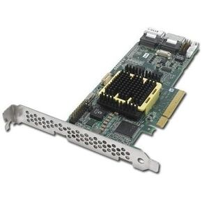 ADAPTEC 5805 8 قنوات SATA/sas 512 ميجابايت PCI Express LP مع كابل SGL
KWD 53
ADAPTEC 5805 8 قنوات SATA/sas 512 ميجابايت PCI Express LP مع كابل SGL
KWD 53
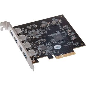 بطاقة Sonnet Allegro Pro USB 3.2 من النوع A PCIe (أربعة موصلات USB فائقة السرعة بسرعة 10 جيجابت في الثانية)
KWD 61.500
بطاقة Sonnet Allegro Pro USB 3.2 من النوع A PCIe (أربعة موصلات USB فائقة السرعة بسرعة 10 جيجابت في الثانية)
KWD 61.500


