- التسوق ، اصبح سهلا.
- /
- احصل على التطبيق!
Motor Drives
M Series - Classic Analog Stepper Drives
Highlights
Pure sinusoidal current control technology with less motor heating
Self-adjustment technology, providing optimal performance with different motors
7 models, covering 20 VDC to 112VDC or 18 VAC to 80VAC operating voltage ranges
Excellent high-speed performance
Smoother movement at low-speed
Lower motor noise and heating than most analog stepper drives on the market
Companion Series
» 2 Phase 17 Stepper Motors
» 2 Phase 23 Stepper Motors
» 2 Phase 34 Stepper Motors
» 2 Phase 42 Stepper Motors
» Unregulated Switching Power Supplies
» Regulated Switching Power Supplies
» Linear Power Supplies
Introduction: With the adoption of its pioneer "pure sinusoidal current control technology" and the latest "self-adjustment technology", M series stepper drives can effectively reduce current ripples and mid-range vibration, enabling different motors to run at optimal performance and with lower heating. They can also eliminate drawbacks of difficulty of driving various motors, such as high heating with smaller inductance motors, low high-speed with large inductance motors, poor performance under low voltage, and high motor heating under high voltage.
Suitable for applications require high reliability, good high speed performance, extremely low cost stepper systems, such as routers, milling or engraving machines, textile equipment, assembly machines, pick-and-place devices, etc.
Available Products in M Series
Model Phase Series Control Type Power Matching Motors
()
Configuration Connector Type
Voltage(V) Current(A)
AC Peak
M542 2 M Step & Dir 24 50 10 42 17 23 DIP switch
M550 2 M Step & Dir 20 50 12 50 14 17 23 DIP switch ×
M752 2 M Step & Dir 20 70 126 52 23 34 DIP switch
M860 2 M Step & Dir 24 80 24 72 172334 DIP switch ×
M880A 2 M Step & Dir 24 80 28 78 23 34 DIP switch
MA860H 2 M Step & Dir 36 80 50 110 24 72 34 42 DIP switch
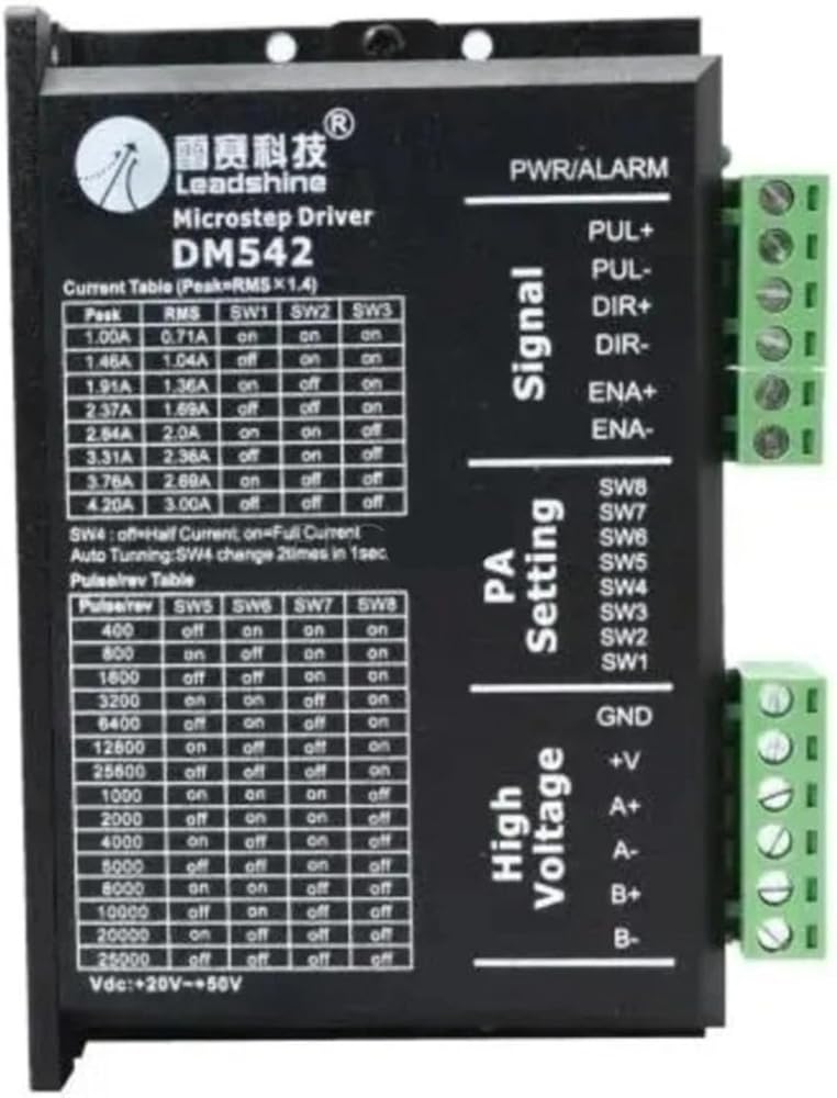
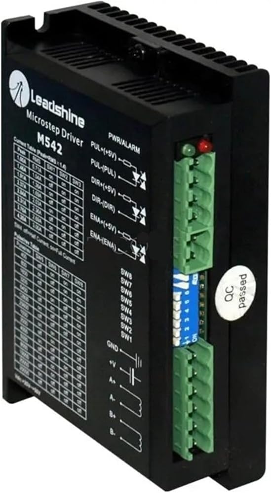
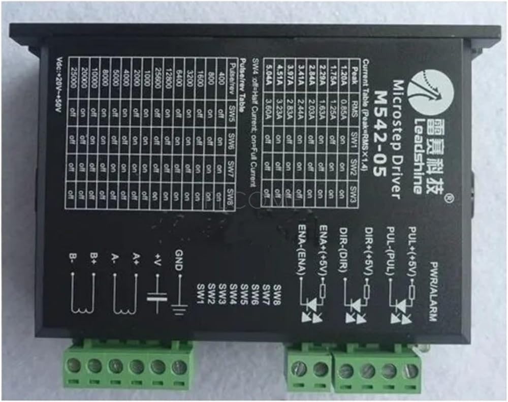
M542
The M542 V2.0 is a high performance microstepping drive based on pure-sinusoidal current control technology. Owing to the above technology and the self-adjustment technology (self-adjust current control parameters) according to different motors, the driven motors can run with smaller noise, lower heating, smoother movement and have better performances at higher speed than most of the drives in the markets. It is suitable for driving 2-phase and 4-phase hybrid stepping motors.
Features:
Extremely cost-effective
Good high speed performance
Supply voltage up to +50 VDC
Output current up to 4.2A
Self-adjustment technology
Pure-sinusoidal current control technology
Pulse input frequency up to 300 KHz
TTL compatible and optically isolated input
Automatic idle-current reduction
15 selectable resolutions in decimal and binary, up to 25,600 steps/rev
Suitable for 2-phase and 4-phase motors
Support PUL/DIR and CW/CCW modes
Short-voltage, over-voltage, over-current protections
Electrical Specifications(Tj = 25oC/77oC)
Parameters
M542 V2.0
Min
Typical
Max
Unit
Output current
1.0
- 4.2 (3.0 RMS)
A
Supply voltage
+20
+36
+50
VDC
Logic signal current
7 10
16
mA
Pulse input frequency
0 - 300
kHz
Isolation resistance
500
Mohm
Connector P1 Configurations
Pin Function
Details
PUL+
Pulse signal: In single pulse (pulse/direction) mode, this input represents pulse signal, each rising or falling edge active (set by inside jumper J1); 4-5V when PUL-HIGH, 0-0.5V when PUL-LOW. In double pulse mode (pulse/pulse) , this input represents clockwise (CW) pulse,active at high level or low level (set by inside jumper J1, J2). For reliable response, pulse width should be longer than 1.5µs. Series connect resistors for current-limiting when +12V or +24V used. The same as DIR and ENA signals.
PUL-
DIR+
DIR signal: In single-pulse mode, this signal has low/high voltage levels, representing two directions of motor rotation; in double-pulse mode (set by inside jumper J3), this signal is counter-clock (CCW) pulse,active at high level or low level (set by inside jumper J1, J2). For reliable motion response, DIR signal should be ahead of PUL signal by 5µs at least. 4-5V when DIR-HIGH, 0-0.5V when DIR-LOW. Please note that rotation direction is also related to motor-drive wiring match. Exchanging the connection of two wires for a coil to the drive will reverse motion direction.
DIR-
ENA+
Enable signal: This signal is used for enabling/disabling the drive. High level (NPN control signal, PNP and Differential control signals are on the contrary, namely Low level for enabling.) for enabling the drive and low level for disabling the drive. Usually left UNCONNECTED (ENABLED).
ENA-
Connector P2 Configurations
Pin Function
Details
+V
Power supply, 20~50 VDC, Including voltage fluctuation and EMF voltage.
GND
Power Ground.
A+, A-
Motor Phase A
B+, B-
Motor Phase B
Current Settings
The first three bits (SW1, 2, 3) of the DIP switch are used to set the dynamic current. Select a setting closest to your motor's required current.
Peak Current
RMS Current
SW1
SW2
SW3
1.00A
0.71A
on
on
on
1.46A
1.04A
off
on
on
1.91A
1.36A
on
off
on
2.37A
1.69A
off
off
on
2.84A
2.03A
on
on
off
3.31A
2.36A
off
on
off
3.76A
2.69A
on
off
off
4.20A
3.00A
off
off
off
Note: Due to motor inductance, the actual current in the coil may be smaller than the dynamic current setting, particularly under high speed condition.
Typical connections:
Mechanical Specifications(unit = mm [inch])
==========
Output Type : 2H
Model Number : M542
DIY Supplies : ELECTRICAL
 ZM-6608 محرك بدون فرش 8A 12-60V لمحرك بدون فرش بقدرة 180 وات
KWD 71
ZM-6608 محرك بدون فرش 8A 12-60V لمحرك بدون فرش بقدرة 180 وات
KWD 71
 BLDC محرك المحرك 70 واط 12-24 فولت وحدة تحكم في مشغل المحرك بدون فرش BLD-70B
KWD 49
BLDC محرك المحرك 70 واط 12-24 فولت وحدة تحكم في مشغل المحرك بدون فرش BLD-70B
KWD 49
 0.4kw MX3G-C40-32MT سيرفو الكل في واحد
KWD 234.500
0.4kw MX3G-C40-32MT سيرفو الكل في واحد
KWD 234.500
 MS9015v3 (RMD-S-9015) BLDC، محرك ميكرو/سيرفو، PTZ محمول باليد، PTZ للتصوير الفوتوغرافي، جراب، قرص دوار، ليدار، UAV، محرك Gimbal (RS485-18bit)
KWD 114.500
MS9015v3 (RMD-S-9015) BLDC، محرك ميكرو/سيرفو، PTZ محمول باليد، PTZ للتصوير الفوتوغرافي، جراب، قرص دوار، ليدار، UAV، محرك Gimbal (RS485-18bit)
KWD 114.500