- التسوق ، اصبح سهلا.
- /
- احصل على التطبيق!
Motor Drives
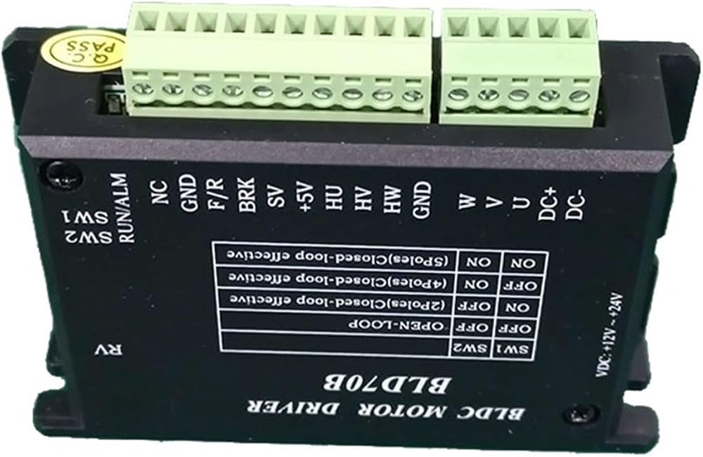
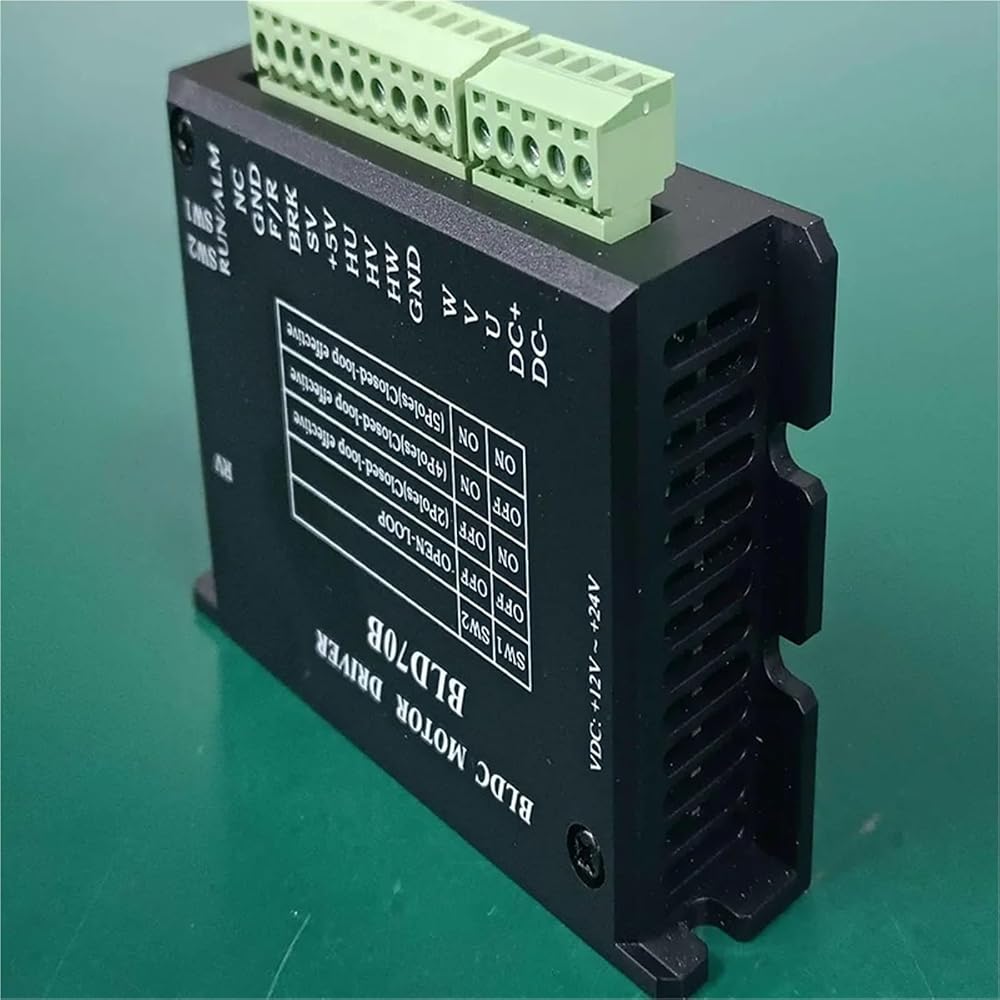
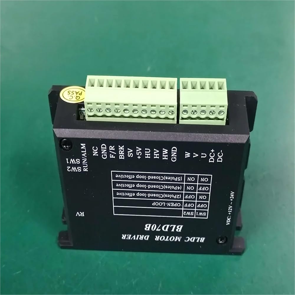
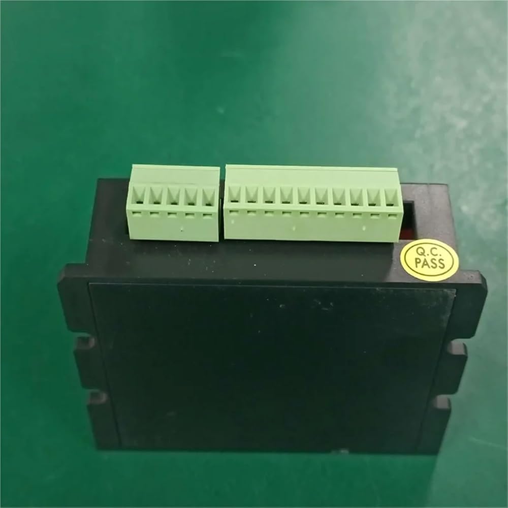
BLDC Motor Driver Controller70W 12-24V Brushless Motor Driver BLD-70B
Note: This linked driver is only applicable to with Hall motors, not applicable to wihtout Hall motors.
brushless motor driver * 1PC
This driver fit for bldc motor with power less of 70W.
1 Introduction
The BLD70B brushless motor driver is designed for 10W~70W low voltage
High-performance, low-cost brushless drivers for brushless motors. The brushless driver can also be extended to support the Modbus communication protocol, which can be used by users in practical applications.
provide more flexible options.
1.1 Product advantages
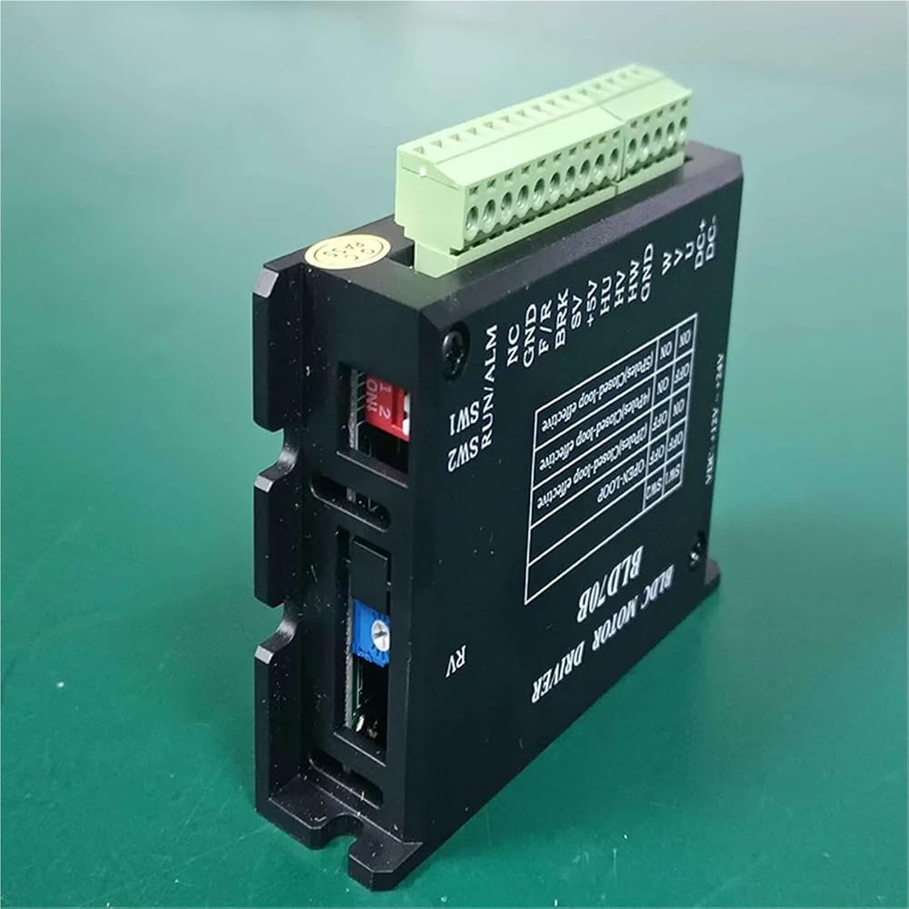
It has both built-in potentiometer RV speed control and external analog speed control
Supports working within the voltage range of 12V~24V
Support the ambient operating temperature range of -20~+55
Speed open and closed loop is optional, in closed-loop control, the rated power is guaranteed, and the speed does not drop when loaded
Supports the drive of brushless motors with rated power ranging from 10W to 70W
5 seconds stall waiting time
BRK external input signal uninterruptible power reset alarm
Support extended Modbus communication protocol, suitable for users to use touch screen or PC control (need to contact business for related content, standard products do not have this function)
Support extended output power adjustment (need to contact business for related content, standard products do not have this function)
2 Electrical performance and environmental indicators
Drive parameters
Input voltage (V) : min. 12V, rated value 24V, max. 30V.
Bus Current (A): 4.2A nominal, 4.5A maximum
Applicable motor speed (rpm): 100rpm (1)
(1) During closed-loop control, the minimum value of the motor speed requires the driver to set the same number of pole pairs as the number of pole pairs of the motor; during open-loop control, this value is related to the design of the motor itself, not necessarily the value in the table; The workmanship of brushless motors is also different. The recommended minimum working speed of the motor is not less than 200 rpm.
Mechanical dimension drawing (Unit mm)
Port Signal Description
power input
GND power input negative pole
24V power input 12V~24V
Motor connection
U brushless motor U phase
V brushless motor V phase
W brushless motor W phase
Hall signal
GND BLDC motor Hall signal ground wire
HW brushless motor Hall signal HW
HV Brushless Motor Hall Signal HV
HU Brushless motor Hall signal HU
+5V brushless motor hall signal power cable
control signal
SV 1) External speed control potentiometer 2) External analog signal input 3) PWM pulse signal speed control
BRK When the BRK terminal is disconnected from the GND terminal, the motor runs, and when it is short-circuited, the motor brakes and stops
When the F/R F/R terminal is disconnected from the GND terminal, the motor rotates forward, and when it is short-circuited, the motor rotates reversely
GND ground wire
NC spare port (input signal)
5 Function selection setting and operation
5.1 Brakes
Disconnect or connect the wires between BRK and GND to control the motor's natural running and quick stop. When connecting the BRK and GND terminals
When disconnected, the motor stops quickly. Otherwise, the motor operates normally.
By connecting a switch between GND and BRK or using to control its on-off, the switch between motor running and quick stop can be realized.
When the driver has a red light alarm, you can also connect BRK and GND, and then release it to restore the alarm without power.
5.2 Direction Control
Connecting or disconnecting the F/R terminal and the GND terminal can control the forward and reverse rotation of the motor.
When the connection line between F/R terminal and GND terminal is disconnected, the motor rotates forward.
When connecting the F/R terminal and the GND terminal, the motor reverses.
6. Selection and setting of speed regulation method
6.1 Speed regulation with built-in potentiometer RV
Turn the built-in speed regulating potentiometer RV clockwise, and the motor starts to run. Continue to rotate clockwise, and the motor speed increases. Rotate the built-in potentiometer RV counterclockwise
The machine speed decreases;
Turn it counterclockwise to the limit position, then the built-in speed regulating potentiometer RV will close and the motor will stop running.
6.2 Speed regulation with external potentiometer
When using an external speed regulating potentiometer, please use a potentiometer with a resistance value of 10k . The middle leading out end of the potentiometer is connected to the SV end, and the leading out ends on both sides
Connect the+5V and GND terminals respectively.
6.3 Speed regulation 0V~5V with external analog signal
When it is necessary to switch to the external analog control speed mode, the built-in potentiometer RV must be closed. Turn the built-in potentiometer RV counterclockwise
Turn to the limit position.
The following figure shows the curve of speed regulation linearity test of an external analog quantity (SV interface). A 24V 3000rpm 4-pole motor is used, and a closed-loop 4-pole motor is set on the board.
6.4 Speed regulation with external PWM pulse signal (recommended speed regulation range: 5%~96%)
The following figure shows the linearity test curve of a duty cycle PWM speed regulation (SV interface)
24V 3000rpm 4-pole motor, closed loop 4-pole motor is set on the board. PWM signal is high
Flat 5V, low level 0V, frequency 3KHz (recommended range 3K~15K Hz)
7 Status indication . exception handling
7.1 Status indication
When the motor has overvoltage, Hall signal error, locked rotor, over temperature and other conditions, the driver will send an alarm signal, and the driver will stop working at the same time.
Description of alarm indication status
The green light flickers regularly, and the output power has reached the P-SV setting value (the standard setting value is fixed at 70W)
The driver fails to receive Hall signal or receives wrong Hall signal when the red light flashes for 5 times
The red light flashes for 8 times, and the motor is locked or the drive circuit is abnormal
The red light flashes 9-15 times, and the peripheral circuit of the master control chip is abnormal
When the green light is flashing, it indicates that the driver is starting to limit current, which will not affect normal use.
7.2 Exception handling
In case of any abnormality in the above table, send a reset command to the driver to eliminate the alarm signal. If the alarm signal cannot be eliminated, handle it according to the following table.
The reset command refers to one of the following three commands, which can enable the drive to remove the alarm.
Adjust the speed regulation of internal potentiometer and external analog quantity to 0 Disconnect after BRK is closed
Power on again
Note that if the internal potentiometer and the external potentiometer are set to 0 at the same time, or BRK is shorted to GND, the driver will not alarm when there is a fault.
Alarm indication exception handling
The red light flashes for 5 times. Please check whether the motor wiring is secure and ensure that the motor is not damaged
The red light flashes for 8 times. Please confirm whether the motor load is too large and the motor is not damaged. If not, please replace it with another one of the same type
Driver experiment
The red light flickers 9-15 times for returning to the for maintenance
==========
Model Number : BLD-70B
Motor Type : Motor
 MG5010E-i10v3 وصول محركات التشفير المزدوجة لمحرك الروبوت الميكانيكي رباعي الأرجل (CAN-18bit-14bit)
KWD 118
MG5010E-i10v3 وصول محركات التشفير المزدوجة لمحرك الروبوت الميكانيكي رباعي الأرجل (CAN-18bit-14bit)
KWD 118
 MS5015v3(RMD-S-5015) BLDC، محرك Gimbal، PTZ محمول باليد، PTZ للتصوير الفوتوغرافي، جراب، قرص دوار، ليدار، UAV، فك تثبيت (CAN-15bit)
KWD 74
MS5015v3(RMD-S-5015) BLDC، محرك Gimbal، PTZ محمول باليد، PTZ للتصوير الفوتوغرافي، جراب، قرص دوار، ليدار، UAV، فك تثبيت (CAN-15bit)
KWD 74
 محرك ME7010 بدون فرش 24 فولت (بدون تشفير)
KWD 66
محرك ME7010 بدون فرش 24 فولت (بدون تشفير)
KWD 66
 محرك سيرفو MS6010v3 BLDC Micro، محرك Gimbal بدون فرش، مع محرك متكامل (محرك بدون سائق)
KWD 66
محرك سيرفو MS6010v3 BLDC Micro، محرك Gimbal بدون فرش، مع محرك متكامل (محرك بدون سائق)
KWD 66