- التسوق ، اصبح سهلا.
- /
- احصل على التطبيق!
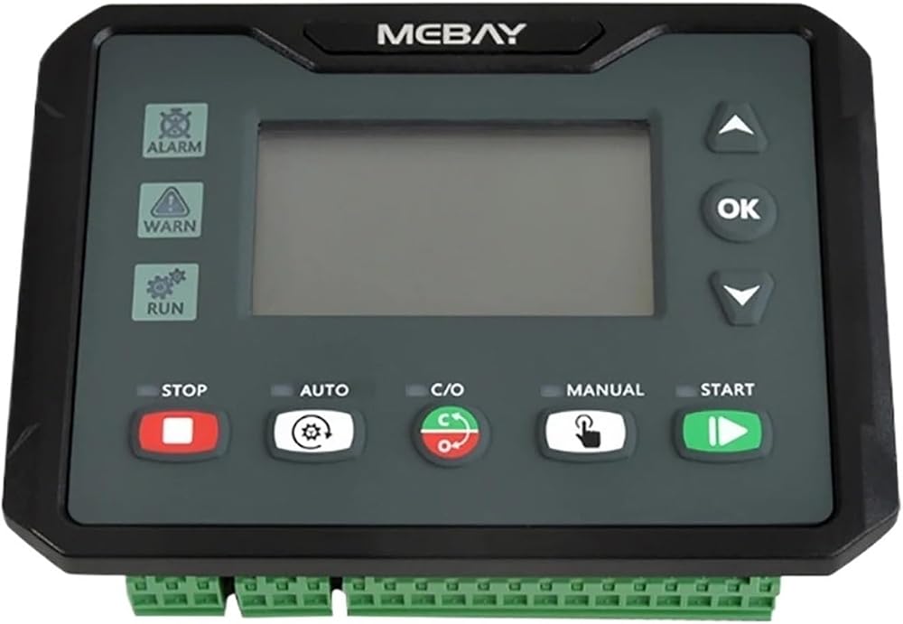
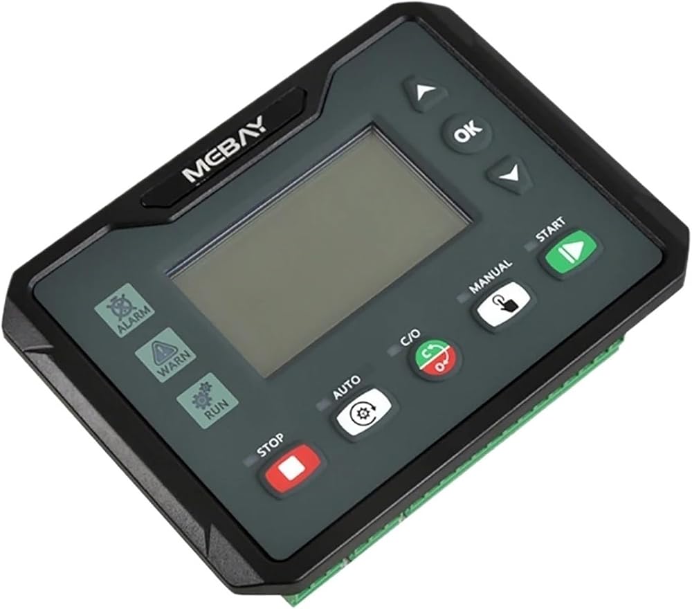
Electronic Engine Control
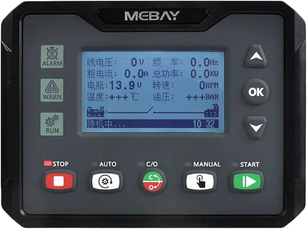
This series controller is specialized for Diesel / Gasoline / Gas Genset Start, Stop, Parameters monitoring, faults-checking as well as data setting.
2.8 inch screen display with UI designis adapted in this controller that the relative failures can be displayed directly. All the parameters can be displayed bysimulated indicators and words. Besides, screen can display various faults in the same time that the genset will be stopped once it can't work smoothly.
There are Chinese/English interface options, more language can be set according to user's request. All the parameters can be configured through the front
face buttons or use programmable interface by RS485 or USB to adjust via PC. It can be widely applied for all kinds of auto control system of gensets.
2. Main Features
There are eight Models under DC4xS/C series.
DC40S: Used for single machine automation. Start/Stop through remote start signal.
DC40SR: Based on DC40S, it adds RS485 port.
DC42S: Based on DC40S, it adds Mains monitoring and AMF (Mains/Generator automatic switching control), especially suitable for the automation system composed by mains and genset.
DC42SR: Based on DC42S, it adds RS485 port.
DC40C: Used for single machine automation. Start/Stop through remote start signal. it adds CAN port.
DC40CR:Based on DC40C, it adds RS485 port.
DC42C: Based on DC40C, it adds Mains monitoring and AMF (Mains/Generator automatic switching control), especially suitable for the automation system composed by mains and genset.
DC42CR: Based on DC42C, it adds RS485 port.
we maily introduce "C" series model:
Dual core 32bit high performance single chip microcomputer.
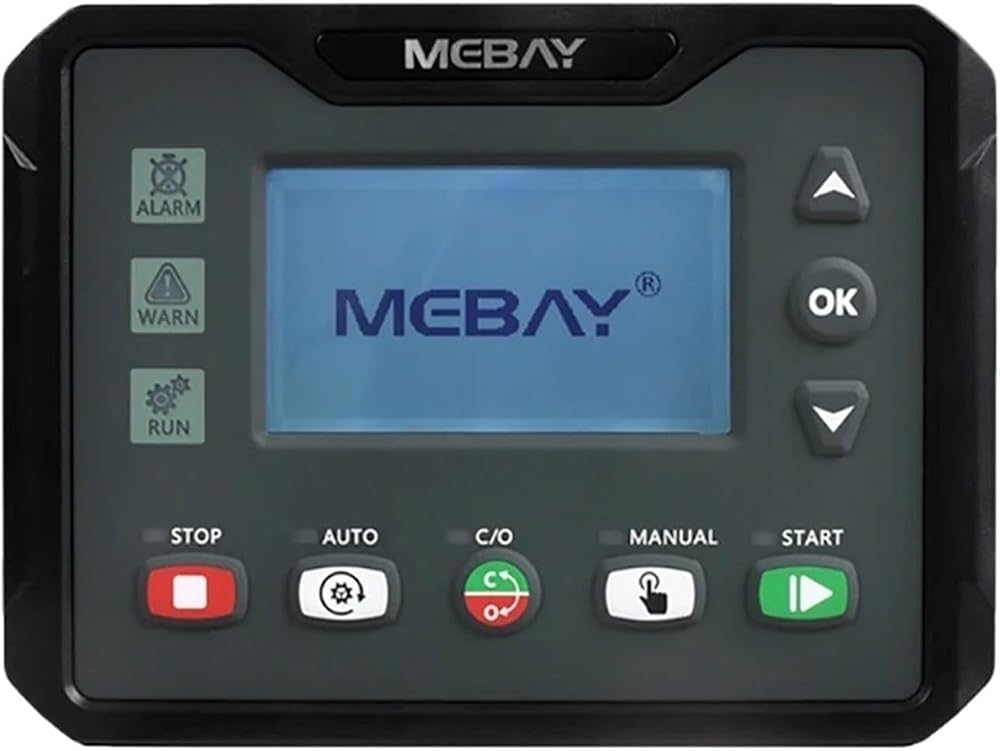
2.8 inch 240 * 128high-resolution screen, Available in 6 languages, user's language set if necessary.
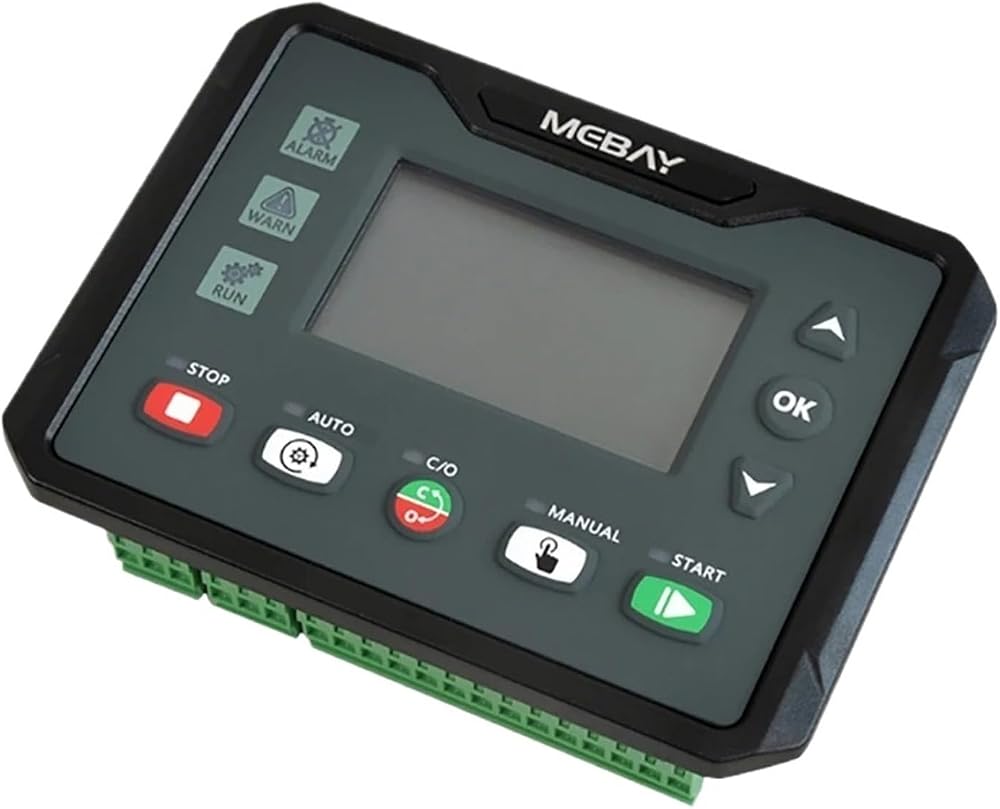
Indicator and number display through UI surface.
Acrylic material is adapted to protect the screen.
Silicone panels;
USB Port: parameters can be set even without power through USB port to monitor in real time.
With RS485 communication port, can achieve "Three Remote" functions via MODBUS protocol.
Standard CAN communication port, built-in J1939 protocol, has matched more than 40 kinds of engines;
Various kinds of parameters display.
Input/output function, status can be shown directly.
Real time clock inside: preset time operate and auto maintenance is available. Genset working plan can be set as per week or month.
Maintenance countdown function, can set maintenance time or date.
The black box function can save the relevant parameters of the unit when the fault alarm occurs in real time, and it is convenient to find the cause of the fault.
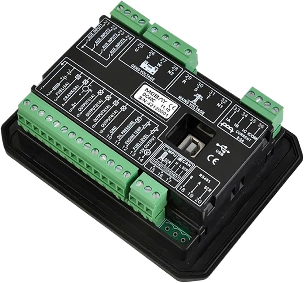
Totally 6relay's output, among which 4 relay output can be self-configurable, each relay can be set as max 20 functions.
With 4 switches input, up to 20 functions optional;
3 sensor simulation input connectors, the oil pressure sensor is compatible with voltage signal input, and various display units can be configured.
Battery charging control function,which can protect the battery according to battery voltage status.
Sensor can be self-defined by front face button or PC software. Adapt to 3P4W,1P2W,2P3W(120V/240V,50/60HZ)
Various of crank conditions (RPM, Frequency, Oil Pressure) can be chosen.
Control Protection: Auto Start/Stop of genset, load transfer (ATS control) and perfect failure display and protection. Standard water-proof rubber gasket. The waterproof can IP54
Module design: All the connections are adapted with European connectors so that installation, connection, repair and replacement can be more easily
3. Parameters Display
Engine RPM
Engine oil pressure
Engine temperature
Engine fuel level
Engine battery voltage
Charging voltage
CAN related parameters(C series only)
Mains Frequency (only for DC42S/C)
Mains phase voltage L-N (only for DC42S/C)
Mains phase voltage L-L (only for DC42S/C)
Generator 3 Phase voltage L-N
Generator 3 Phase voltage L-L
Generator 3 phase current A
Generator Frequency Hz
Generator Power Factor COS
Generator active power KW
Generator apparent power KVA
Generator reactive power KVar
Real-time load rate %
Current load rate %
Average loading rate %
Current consumption KWH
Total consumption KWH
Total Crank times
Cumulative power on time of controller
Current running time
Total running time
Maintenance notice
Switches input status display
Output status display of relays
Current date and time;
4. Protection
Over speed
Under speed
Low oil pressure
High temperature
Low fuel level
External emergency alarm
D+ open
RPM Lost
Sensor Open
Over Frequency
Under Frequency
Over voltage
Under voltage
Over current
Non-balance of current
Over power
Maintenance expire
Low water level alarm
Emergency Stop
Crank failure
Battery over voltage
Battery under voltage
The charger fails to charge
Charger charging failure
Stop Failure
ECU alarm failure
ECU communication Failure
 DSE701K AS 701AS GENSERATOR SESSITAL SESSIONDARTAR CONTROLLER BUND BUNTING MODULE DSE701MS 701MS DIESEL Genet Parts (DSE701K AS)
KWD 41.500
DSE701K AS 701AS GENSERATOR SESSITAL SESSIONDARTAR CONTROLLER BUND BUNTING MODULE DSE701MS 701MS DIESEL Genet Parts (DSE701K AS)
KWD 41.500
 DC40D DC40DR DC42D DC42DR MK3 وحدة تحكم مولد ديزل وحدة تحكم Genset Auto Control مراقبة المعلمات Panal (DC42DR MK3)
KWD 62
DC40D DC40DR DC42D DC42DR MK3 وحدة تحكم مولد ديزل وحدة تحكم Genset Auto Control مراقبة المعلمات Panal (DC42DR MK3)
KWD 62
 وحدة التحكم لـ 4 AMF 20 ، وحدة التحكم في المند AMF20
KWD 198.500
وحدة التحكم لـ 4 AMF 20 ، وحدة التحكم في المند AMF20
KWD 198.500
 وحدة التحكم في وحدة التحكم في HAT560N ATS مع عرض قياس تلقائي للوظيفة القابلة للتكوين (HAT560N)
KWD 109.500
وحدة التحكم في وحدة التحكم في HAT560N ATS مع عرض قياس تلقائي للوظيفة القابلة للتكوين (HAT560N)
KWD 109.500