- Shopping, made easy.
- /
- Get the app!
Overview
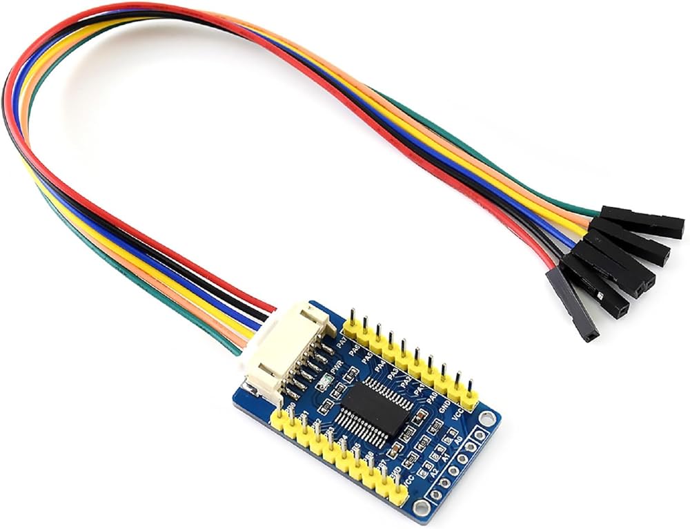
The MCP23017 IO Expansion Board expands 2 signal pins as 16 I/O pins based on the I2C bus, supports using 8 Expansion Boards at the same time, which can be expanded to 128 I/O ports.
Features
I2C controlled, expands 2 signal pins as 16 I/O pins
I2C address configurable by shorting the A0/A1/A2 jumpers
Provides two connector options: PH2.0 terminal and/or solder pads, allows multi I2C modules to be stacked
Onboard voltage translator, compatible with 3.3V/5V level
Comes with development resources and manual (examples for Raspberry Pi / micro:bit / Arduino / STM32)
Online Tutorial/Online Document: n9.cl/df3o3
Specifications
Operating voltage: 5V/3.3V
Interface: I2C
Interrupt pins: INTA, INTB
Expansion I/Os: 16
Dimension: 38mm × 23mm
Mounting hole size: 2.0mm
Interface Definition
PIN---I2C
VCC---Power supply, 3.3V/5V
GND---Ground
SDA---I2C data line
SCL---I2C clock line
INTA---PA group interrupt output
INTB---PB group interrupt output
Package Content
MCP23017 IO Expansion Board x1
PH2.0 20cm 6Pin x1
Question: How to connect multiple modules in parallel at the same time for MCP23017?
Answer:
The I2C interface can be directly connected in parallel. Note that if more than one MCP23017 module is connected in parallel at the same time, the I2C addresses of the modules need to be modified to be different, and up to 8 can be connected at the same time. Modify the module i2c address method: not connect or short A0, A1, A2, high level when it is not connected, and is low when it is short, the total can be set to 2x2x2 different i2c address.
 CSI FPC Flexible Cable For Raspberry Pi 5, 22Pin To 15Pin, 0.5 M Length, Suitable For CSI Camera Modules, Connecting CSI Camera Module to Raspberry Pi 5 or Compute Module 4, 500MM/50CM/0.5M Length
KWD 3.500
CSI FPC Flexible Cable For Raspberry Pi 5, 22Pin To 15Pin, 0.5 M Length, Suitable For CSI Camera Modules, Connecting CSI Camera Module to Raspberry Pi 5 or Compute Module 4, 500MM/50CM/0.5M Length
KWD 3.500
 Waveshare PCIe to M.2 Adapter for Raspberry Pi 5, Supports NVMe Drive Protocol Compatible with 2230/2242 Size M.2 Solid State Drive, High-Speed Reading/Writing, Gen2 and Gen3 Modes, HAT + Standard
KWD 6
Waveshare PCIe to M.2 Adapter for Raspberry Pi 5, Supports NVMe Drive Protocol Compatible with 2230/2242 Size M.2 Solid State Drive, High-Speed Reading/Writing, Gen2 and Gen3 Modes, HAT + Standard
KWD 6
 Built-in WiFi Raspberry Pi Pico W Microcontroller Board with Pre-soldered Header, Based on Official RP2040 Dual-core Processor, Dual-Core Arm Cortex M0+ Processor, with USB Cable
KWD 6
Built-in WiFi Raspberry Pi Pico W Microcontroller Board with Pre-soldered Header, Based on Official RP2040 Dual-core Processor, Dual-Core Arm Cortex M0+ Processor, with USB Cable
KWD 6
 ESP32-S3 7inch Capacitive Touch Display, ESP32 Development Board with 7inch LCD Screen 800×480, 32-bit LX7 Dual-Core Processor, Up to 240MHz Frequency, Supports WiFi & Bluetooth, with Onboard Antenna
KWD 20.500
ESP32-S3 7inch Capacitive Touch Display, ESP32 Development Board with 7inch LCD Screen 800×480, 32-bit LX7 Dual-Core Processor, Up to 240MHz Frequency, Supports WiFi & Bluetooth, with Onboard Antenna
KWD 20.500