- التسوق ، اصبح سهلا.
- /
- احصل على التطبيق!
Resistor Chip Arrays
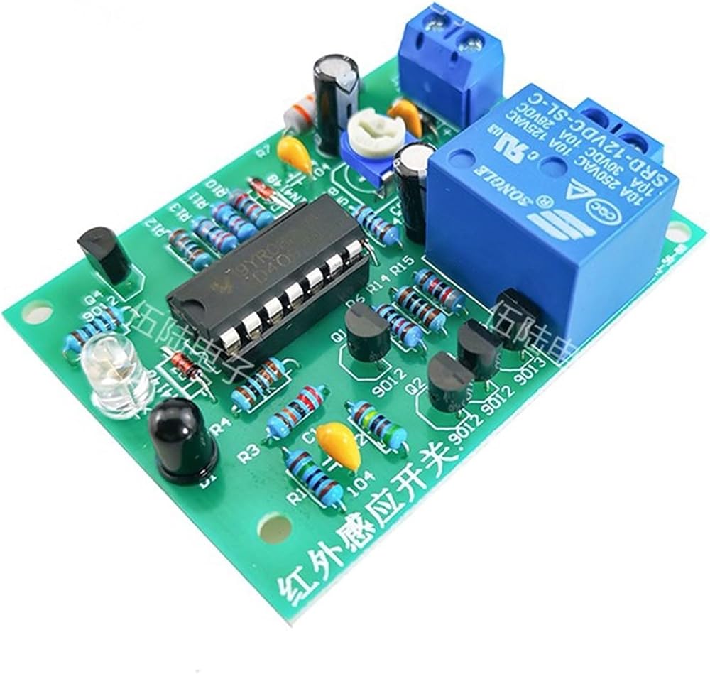
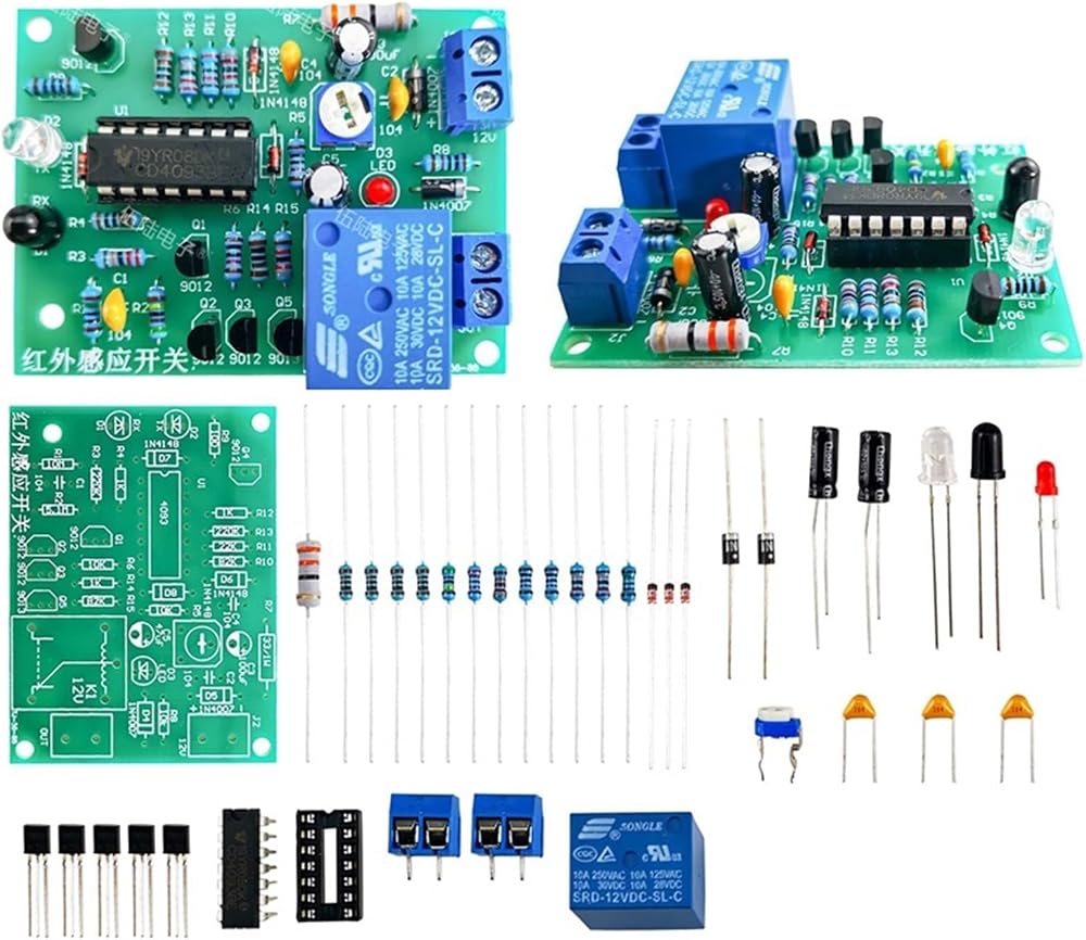
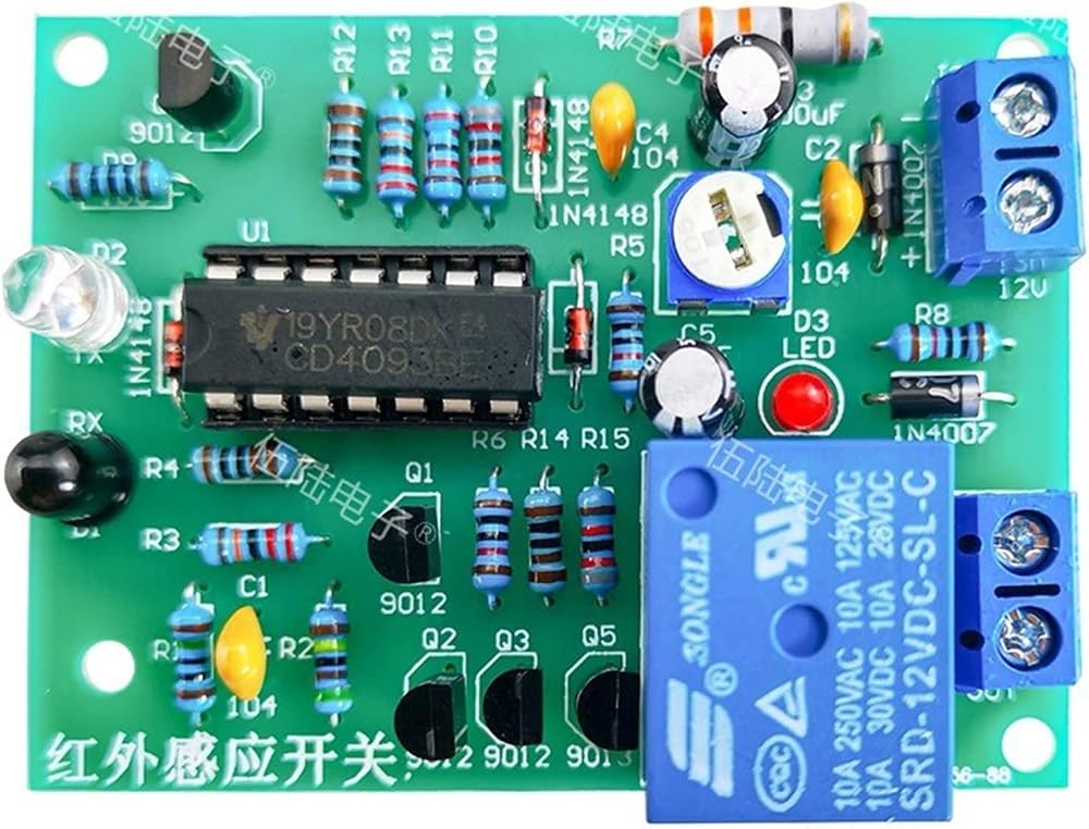
Product name: infrared induction switch proximity switch DIY welding kit
Product model: TJ-56-88
Working voltage: DC12V
PCB size: 58 * 44mm
Quiescent current: 28mA
Pick-up current: 70mA
Reference value of sensing distance: 15cm
Relay contact capacity: 10A/250V
Delay time: 0~40S adjustable
Description:
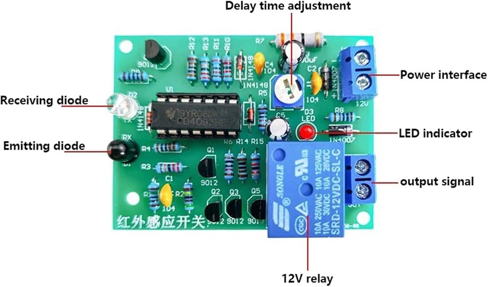
The infrared induction switch is used to determine whether there is an object in front by detecting whether the infrared signal emitted is reflected, thus controlling the switch action of the relay. It can be used on the sensing faucet, automatic hand dryer and other equipment.
Circuit description:
The whole system consists of power supply circuit, infrared induction circuit, delay circuit and switch control circuit. 1. Power circuit: J2 input 12V power supply, D5 can prevent the polarity of the power supply from being reversed, R7 is the current limiting resistance, C2 and C4 filter. Infrared induction circuit: The oscillator is composed of U1C, R10, R11, D6 and C5, and the pulse signal is output from the 10 pins of U1. After being amplified by Q4, the infrared transmitting tube D2 is driven to transmit infrared signals into space. If the signal is not blocked by an obstacle, the infrared receiving tube D1 cannot receive the signal, so the following circuit does not work; When there is an obstacle in front of D2, the transmitted infrared signal will be sent back by the obstacle, and will be received by D1. The received signal will be amplified by Q1 and Q2, and finally the amplified infrared signal will be output at the R3 end, and then the frequency will be selected by U1A and reshaped by U1D, and then output at the 11 pin of U1. 3. Delay circuit: R5, VR1 and C3 constitute a delay circuit. Adjusting VR1 can adjust the delay time after each action. The design delay time of this circuit is adjustable in the range of 0-40S. Due to certain error in component parameters, the time delay time will be s
 مربع Triode Kit to-92 حزمة العناصر ترانزستور مجموعة العناصر صندوق 10 أنواع ، 500 في المجموع
KWD 19
مربع Triode Kit to-92 حزمة العناصر ترانزستور مجموعة العناصر صندوق 10 أنواع ، 500 في المجموع
KWD 19
 5pcs IRF9530NPBF IRF9530N IRF9540N IRF9640 TO220 P-channel FET (IRF9540N)
KWD 15.500
5pcs IRF9530NPBF IRF9530N IRF9540N IRF9640 TO220 P-channel FET (IRF9540N)
KWD 15.500
 20pcs LP2178A LP2178 SMD SOP8 AC-DC غير معزولة
KWD 16.500
20pcs LP2178A LP2178 SMD SOP8 AC-DC غير معزولة
KWD 16.500
 20pcs TP4333 4333 SOP8 4.2V 1A Power Power Boost IC IC
KWD 16
20pcs TP4333 4333 SOP8 4.2V 1A Power Power Boost IC IC
KWD 16