- التسوق ، اصبح سهلا.
- /
- احصل على التطبيق!
Product Introduction
Dual H-bridge, can drive two DC motors at the same time, single channel 7A high power
Wide voltage 6.5V~27V
Optocoupler isolation input signal
With isolation and undervoltage protection
Comply with electromagnetic compatibility EMC design specifications, with electrostatic discharge circuit, stable and reliable, industrial grade
Product highlights
1. Dual H-bridge, can drive two DC motors at the same time, single channel 7A current, high power
2. Wide voltage input 6.5V~27V
3. Signal optocoupler isolation input, can be directly controlled by IO port without interference
4. Undervoltage protection, high current burns the module
5. High-power TVS and electrostatic discharge circuit, suppress transient interference pulses and static electricity, enhance EMC performance, stable and reliable products, industrial grade design
Product parameters
1. Supply voltage 6.5V-27V, the power supply cannot be reversed or exceed 27V, otherwise the module may burn out. It is recommended to connect 1 fuse in series at the power input end
2. Dual motor interface, each rated output current is 7A, peak current is 50A, the motor interface cannot be short-circuited, and a 10A fuse is recommended to be connected in series
3. The control signal voltage is 3-6.5V, which are the enable signal and the forward and reverse control signal respectively
4. The enable signal end (ENA) input PWM adjustable speed, PWM frequency range is 0-10KHZ, PWM small pulse width is 10us
5. Working temperature -25℃-80℃
6. Product size: 55*55*16mm (length, width and height)
7. Mounting hole diameter: 3mm, pay attention to the short circuit of the back circuit during installation, you can add an insulating pad or copper column to raise the circuit board
8. Weight: 20 g
Suitable motor parameters
Motors with a rated voltage of 24V are suitable for motors with a rated power of 115W or less or rated current of 7A or less to work at full capacity for a long time
Motors with a rated voltage of 12V are suitable for motors with a rated power of 40W or less or rated current of 7A or less to work at full capacity for a long time
Notes:
1. The driver power supply cannot be connected upside down. It is recommended to connect a fuse in series at the power interface, and the voltage should be between 6.5 and 27V. If the voltage is overvoltage, the drive module may be burned when powered on.
2. It is recommended that the rated output current of the power supply be more than 2 times the rated current of the motor, so as not to cause the power supply to fail to provide the current required when the motor starts, resulting in the power supply voltage falling and the power supply voltage not reaching the input voltage required by the driver, so that the drive module performs undervoltage protection. Turn off the output and cause the motor to stall.
3. The motor interface cannot be short-circuited, otherwise the drive module may be burned. It is recommended to connect a 10A fuse in series at the motor interface.
4. When switching between forward and reverse, you need to brake above 0.1S before reversing. You can't reverse the motor before it stops, otherwise the driver may be damaged.
5. When the drive module is powered off, do not directly or indirectly rotate the motor at high speed, otherwise the electromotive force generated by the motor may burn the drive module. If the application needs to rotate the motor at high speed when the drive module is powered off, it is recommended to connect a relay in series (NO and COM ends are connected in series) to the motor interface of the driver, and the relay coil is shared with the driver. In this way, when the power supply is powered off, the relay will disconnect the driver from the motor.
6. Be careful not to let the driver get wet, do not let the components on the driver board short circuit, and do not touch the pins and pads of the components on the board with your hands.
 2pcs 35 ثانية مسجل صوتي للحيوانات المحشوة ، مربع الصوت للهدايا القابلة للتسجيل ، مسجل لعبة forcrafters ، الهواة ، المحشو ، الحيوانات ، العروض المدرسية ، العناصر الشخصية ، إلخ.
KWD 5.500
2pcs 35 ثانية مسجل صوتي للحيوانات المحشوة ، مربع الصوت للهدايا القابلة للتسجيل ، مسجل لعبة forcrafters ، الهواة ، المحشو ، الحيوانات ، العروض المدرسية ، العناصر الشخصية ، إلخ.
KWD 5.500
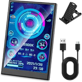 سعة 3.5 بوصة IPS شاشة USB Mini لا يوجد تثبيت Aida64 حالة شاشة شاشة الكمبيوتر شاشة TEMP شاشة PC PC PCARD مع حامل ، كابل USB ، دليل
KWD 11.500
سعة 3.5 بوصة IPS شاشة USB Mini لا يوجد تثبيت Aida64 حالة شاشة شاشة الكمبيوتر شاشة TEMP شاشة PC PC PCARD مع حامل ، كابل USB ، دليل
KWD 11.500
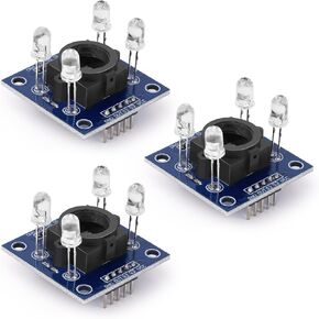 3pcs GY-31 TCS3200 MODEL SESSOR MODULE MODULE MONDITION MONDULE 3V-5V Sensor مع واجهة SPI , لـ Arduino
KWD 7.500
3pcs GY-31 TCS3200 MODEL SESSOR MODULE MODULE MONDITION MONDULE 3V-5V Sensor مع واجهة SPI , لـ Arduino
KWD 7.500
 USB C Power Meter USB C Tester ، 3-36V 0-12A PD3.1 QC4.0 PDO فك تشفير عالية الدقة في الجهد الجهد الحالي للقياس الجهد الحالي فولتميتر مقياس الذراع الرقمي لمكشاف MultiMeter لكابل الشاحن
KWD 8
USB C Power Meter USB C Tester ، 3-36V 0-12A PD3.1 QC4.0 PDO فك تشفير عالية الدقة في الجهد الجهد الحالي للقياس الجهد الحالي فولتميتر مقياس الذراع الرقمي لمكشاف MultiMeter لكابل الشاحن
KWD 8


