- التسوق ، اصبح سهلا.
- /
- احصل على التطبيق!
Instruction:
1.Remove basically all outside screws for your Anet A8 control box
2.Take pictures of existing board wiring
3.Unscrew two large 12 / 14GA wires on the board labeled HOT BED
4.Screw these two wires into the new MOSFET board labeled HOT BED
5.Connect the small jumper wires (white) to the control board where 6.you just remove the two wires and screw them down. Note the 7.polarity on each board. Match ( + ) to ( + ) and ( - ) to ( - )
8.Find 2 x 6 - 8 inches pieces of 12 or 14 AWG wire
9.Run one of the 6 inches wires to the power supply ( + ), screw in. 10.The other side to the (+) DC on the new MOSFET board. Repeat for the negative wire (-) to (-)
11.many people use Velcro to secure the new board to the top of the control box.
12.Put everything back together
13.when complete, you'll see a blue light activate for signal from inside the box when the bed heater is activated by the control board
Feature:
1.Effectively solve the problem that the heat bed power is too large and the load current issue
2.Helps 3D printers with controller boards (capable of max 15A) become more powerful
3.With this additional module, the maximum current on the board can reach 25A
Note:
1.This module under the premise of normal cooling, found at I (Max) = 25A stable work situation, the process of using the current not exceed 25A.
2.If your total power usage is 240W, and you have a 12V power supply, that means you need at least 20A (20x12=240W)
Package includes:
2 x Heated Bed Module
2 x Connection cable for input signal
8 x Fork type cold press terminal
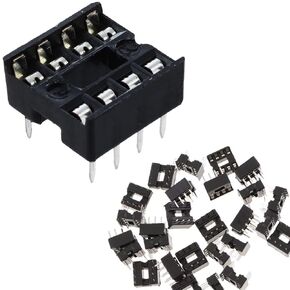 DAOKAI 50 قطعة 8Pin IC رقاقة محول مأخذ التوصيل 2.54 مللي متر الملعب نوع المقبس صف مزدوج دبابيس مسطحة لحام الدوائر المتكاملة IC مآخذ موصل
KWD 2.500
DAOKAI 50 قطعة 8Pin IC رقاقة محول مأخذ التوصيل 2.54 مللي متر الملعب نوع المقبس صف مزدوج دبابيس مسطحة لحام الدوائر المتكاملة IC مآخذ موصل
KWD 2.500
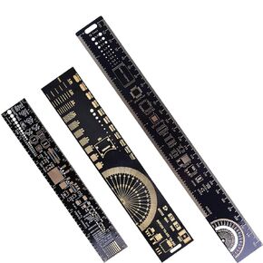 3 قطعة PCB حاكم 3 أحجام 15/20/25 سنتيمتر 5.9/7.8/9.8in متعددة الوظائف الهندسة حاكم المقاوم مكثف رقاقة IC أداة قياس لوحة دوائر كهربائية مطبوعة حاكم
KWD 4
3 قطعة PCB حاكم 3 أحجام 15/20/25 سنتيمتر 5.9/7.8/9.8in متعددة الوظائف الهندسة حاكم المقاوم مكثف رقاقة IC أداة قياس لوحة دوائر كهربائية مطبوعة حاكم
KWD 4
 10 قطعة IIC I2C محول المستوى المنطقي 4 قنوات ثنائية الاتجاه وحدة الجهد المستوى 3.3-5 فولت شيفتر لاردوينو ، مع كابل دوبونت
KWD 3.500
10 قطعة IIC I2C محول المستوى المنطقي 4 قنوات ثنائية الاتجاه وحدة الجهد المستوى 3.3-5 فولت شيفتر لاردوينو ، مع كابل دوبونت
KWD 3.500
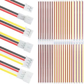 JST PH 2.0 موصل قابس كهربائي صغير للذكور والإناث 2/3/4 دبوس توصيل تباعد 2.0 مم 26AWG 20 سم كابل سلك سيليكون (30 زوج) لإضاءة LED
KWD 4.500
JST PH 2.0 موصل قابس كهربائي صغير للذكور والإناث 2/3/4 دبوس توصيل تباعد 2.0 مم 26AWG 20 سم كابل سلك سيليكون (30 زوج) لإضاءة LED
KWD 4.500


