- التسوق ، اصبح سهلا.
- /
- احصل على التطبيق!
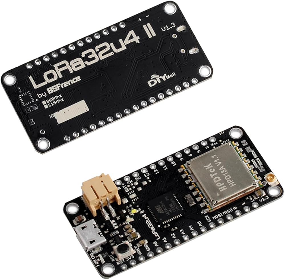
DIYmall LoRa32u4 II LoRa Development Board Low Consumption Atmega/328 SX1276 HPD13 Module with 915MHz LoRa Antenna for Arduino LoRa/WAN
Description:
ATmega/32u4 at 8MHz with 3.3V logic/power
3.3V regulator with 500mA peak current output
USB native support, comes with USB bootloader and serial port debugging
Built in 100mA lipoly charger with charging status indicator LED
Reset button
HPD13:
Receive current: 10 ~ 14mA
Interface Type: SPI
Operating temperature: -40℃ to + 85℃
Digital RSSI function
Automatic frequency correction
Automatic gain control
Radio wake-up function
Low voltage detection and temperature sensor
Fast wakeup with frequency hopping
Highly configurable packet handlers
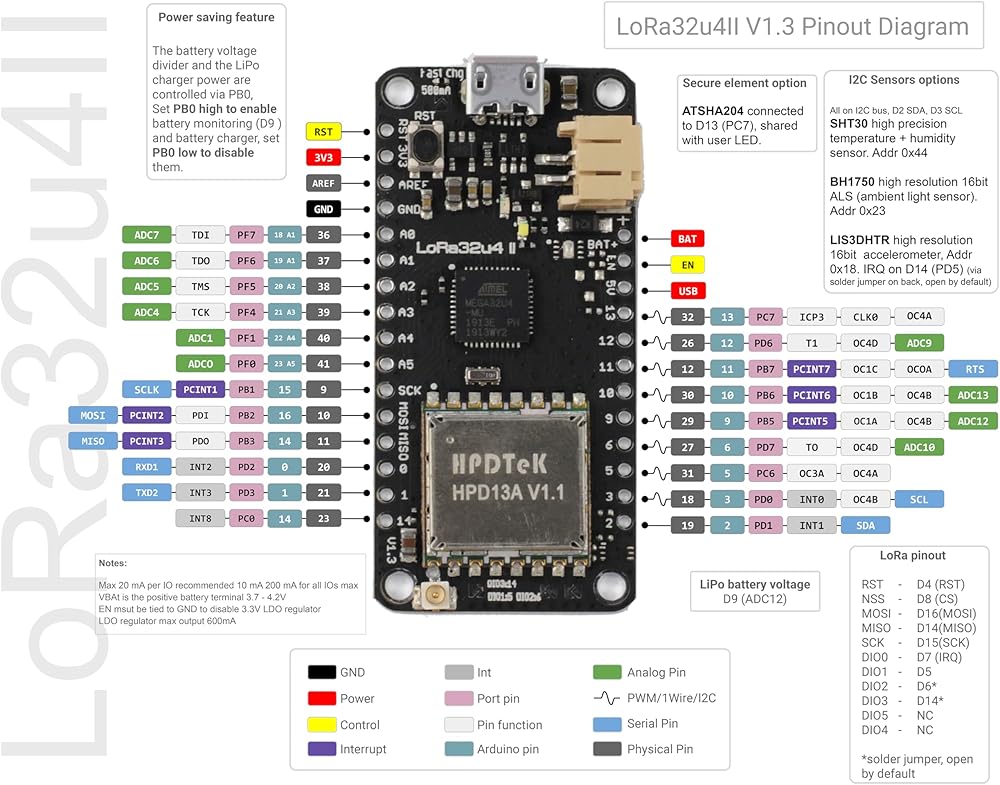
LoRa32u4II revision 1.3 improvements :
1. LOW POWER
1.1. The battery monitoring circuit is now active and enabled by the previously unused pin PB0 (not broken-out on headers), it must be enabled (high) to allow battery monitoring.
1.2. The battery charger is now controlled, it must be enabled (high) by PB0 to allow battery charging.
1.3. The LDO has been replaced for an ultra low IQ LDO (0.5uA).
1.4. Overall sleep current has been lowered from 260.2uA to 183.8uA (tested with Atmega32u4 in watchdog sleep mode @ 8MHz and LoRa circuit in sleep mode).
2. USAGE
2.1. LoRa DIO1 is now connected by default to Atmega/32u4 pin 5 (PC6) allowing direct use of LMIC and other LoRaWAN libraries without soldering, it is still possible to disable this link by opening the DIO1 solder jumper on topside.
2.2. LoRa DIO2 and DIO3 are now routing to Atmega32u4 pin 6 (PD7) and 14 (PD5), solder jumpers are open by default (these DIO pins are rarely used).
2.3. Atmega32u4 pins 0 (PD2),1 (PD3) for UART and 2 (PD1), 3 (PD0) for I2C are now free for use.
2.4. LoRa DIO pins solder jumpers have been moved on topside for better accessibility.
2.5. Pull-up resistors (4.7K) have been added on the I2C bus.
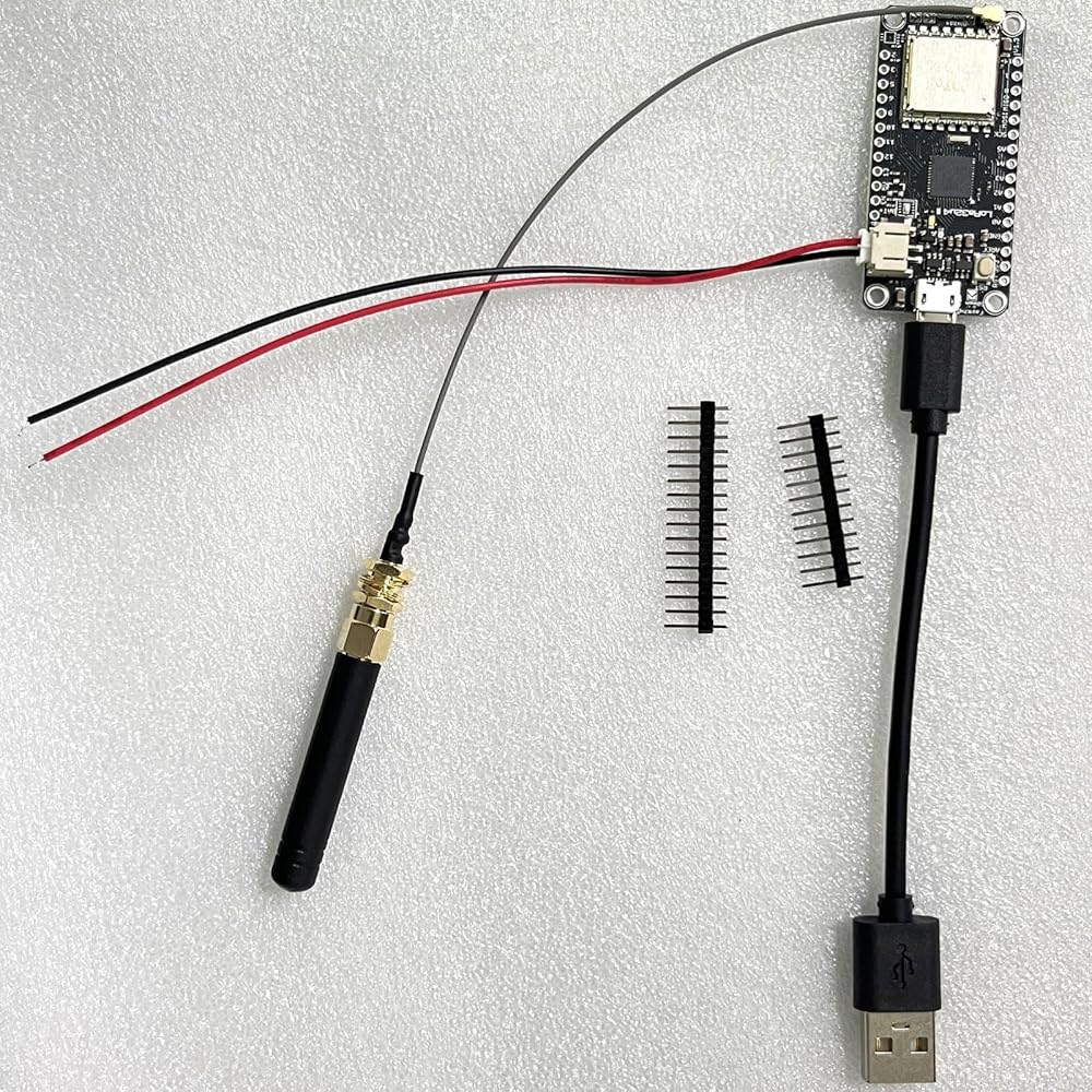
2.6. The antenna uFL connector has been moved on topside to ease access.
 مجموعتان مجمعتان ESP32 OLED واي فاي Lora Kit 0.35 بوصة شاشة OLED ESP-32S متوافقة مع بلوتوث CP2102 لوحة تطوير Lora SX1276 915MHZ/868MHZ جهاز إرسال هوائي لـ Arduino ESP8266 NodeMCU
KWD 20.500
مجموعتان مجمعتان ESP32 OLED واي فاي Lora Kit 0.35 بوصة شاشة OLED ESP-32S متوافقة مع بلوتوث CP2102 لوحة تطوير Lora SX1276 915MHZ/868MHZ جهاز إرسال هوائي لـ Arduino ESP8266 NodeMCU
KWD 20.500
 -5%
داي مول مستشعر المسافة بالليزر تي اف ميني بلس من بينيواك، مقاوم للماء بتصنيف IP65 لمقاومة المياه والغبار 12 متر 1000 هرتز UART لاردوينو راسبيري باي STM32
KWD 19.500
-5%
داي مول مستشعر المسافة بالليزر تي اف ميني بلس من بينيواك، مقاوم للماء بتصنيف IP65 لمقاومة المياه والغبار 12 متر 1000 هرتز UART لاردوينو راسبيري باي STM32
KWD 19.500
 DOIT DEVIT V1 ESP32-WROOM-32 ESP32S Wifi + Bluetooth Dev Module CP2102 لـ Arduino
KWD 7
DOIT DEVIT V1 ESP32-WROOM-32 ESP32S Wifi + Bluetooth Dev Module CP2102 لـ Arduino
KWD 7
 وحدة قيادة سيارات Diymall L298n Module Dual H Bridge Stepper لسيارة Arduino الذكية
KWD 3
وحدة قيادة سيارات Diymall L298n Module Dual H Bridge Stepper لسيارة Arduino الذكية
KWD 3