- التسوق ، اصبح سهلا.
- /
- احصل على التطبيق!
Description:
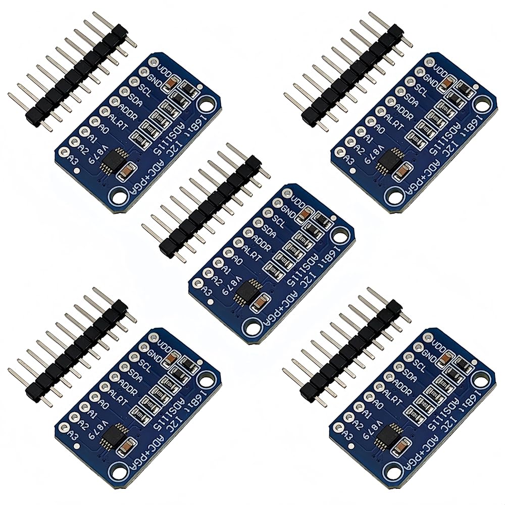
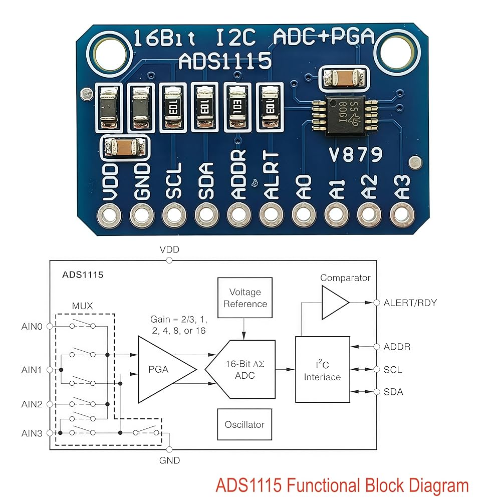
Model: ADS1115
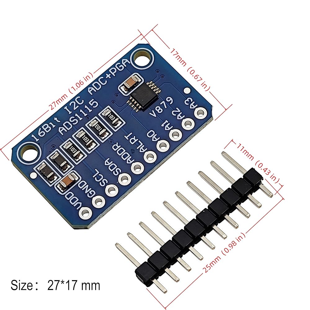
Size: 27*17mm
Weight: 3g
Color: blue
Wide power supply voltage: 2V to 5.5V
Channel input voltage: 0-VDD
Interface type: I2C (Pin optional address)
Channels: 4 channels (AN0 AN1 AN2 AN3)
ADC bit rate: 16 bits
Low current consumption: Continuous mode: only 150μA; Single shot mode: automatic shutdown.
Programmable data rate: 8sps-860sps
Operating temperature range: -40°C to +120°C
Input: 4 single-ended channels or 2 differential channels
I2C 7-bit address 0x48-0x4B
Input range programmable control, 7 input ranges:
-0.256V ~ + 0.256V
-0.512V ~ + 0.512V
-1.024V ~ + 1.024V
-2.048V ~ + 2.048V
-4.096V ~ + 4.096 V
-6.144V ~ + 6.144V
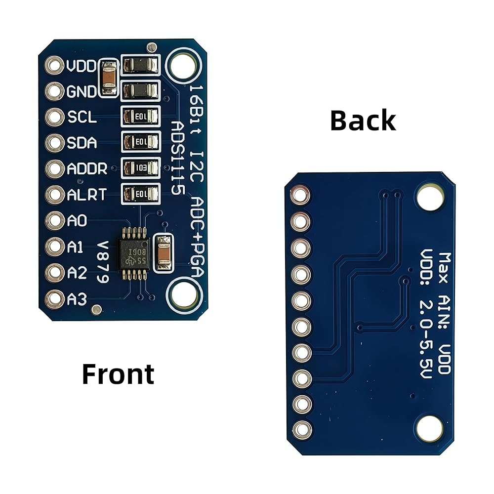
Pin Description:
VDD: Positive (3.3V/5V)
GND: Ground, Negative
SCL: IIC clock line
SDA: lIC data cable
ADDR: Determine IIC slave address
ALRT: Digital comparator output or conversion ready
A0: Differential channel 1, positive input or single ended channel 1 input
A1: Differential channel 1, negative input or single ended channel 2 input
A2: Differential channel 2, positive input or single ended channel 3 input
A3: Differential channel 2, negative input or single ended channel 4 input
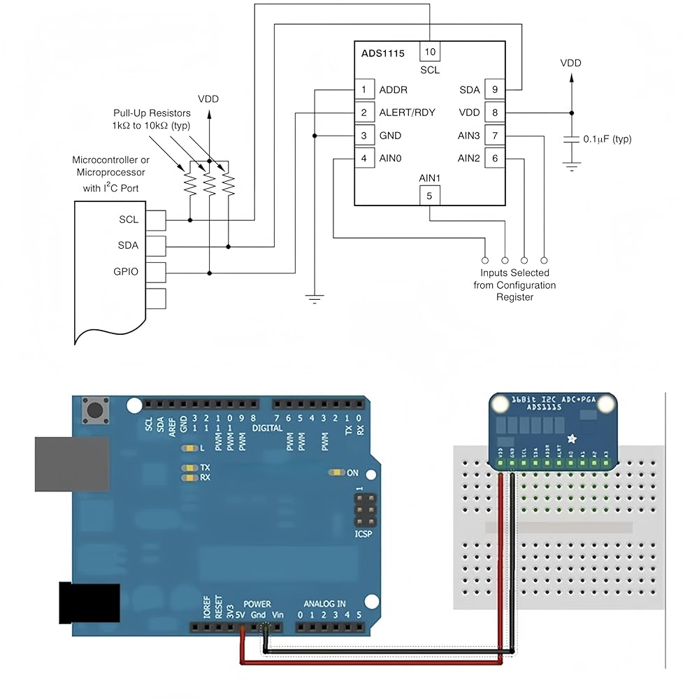
Instructions:
The module IIC bus has a pull-up resistor, so users do not need to pull it up. The default 7-bit IIC address of the module is 0x48 (1001000), and the chip uses a clever addressing method that allows the use of one address pin (ADDR) to achieve four different addresses
When ADDR is connected to ground, the IIC address is 0 × 48 (1001000)
When ADDR is connected to VDD, the IIC address is 0 × 49 (1001001)
When ADDR is connected to SDA, the IIC address is 0 × 4A (1001010)
When ADDR is connected to SCL, the IIC address is Ox4B (1001011)
 بريدجولد 40 قطعة (20 قطعة 74HCxx+20 قطعة 74LSxx) مجموعة متنوعة من سلسلة لوجيك اي سي
KWD 4.500
بريدجولد 40 قطعة (20 قطعة 74HCxx+20 قطعة 74LSxx) مجموعة متنوعة من سلسلة لوجيك اي سي
KWD 4.500
 SD80 AC Pointer AMMETER 10A 20A 30A 50A 60A 100/5A DH80 AMPERAGE1PCS (AC 10A)
KWD 22.500
SD80 AC Pointer AMMETER 10A 20A 30A 50A 60A 100/5A DH80 AMPERAGE1PCS (AC 10A)
KWD 22.500
 RELAY 10PCS RELAY OZ-SS-112L OZ-SS-124L OZ-SS-112L1 OZ-SS-124L1 OZ-SS-112LM1 OZ-SS-124LM1 16A 240VAC (الحجم: OZ-SS-124L DIP-8 16A)
KWD 17
RELAY 10PCS RELAY OZ-SS-112L OZ-SS-124L OZ-SS-112L1 OZ-SS-124L1 OZ-SS-112LM1 OZ-SS-124LM1 16A 240VAC (الحجم: OZ-SS-124L DIP-8 16A)
KWD 17
 5pcs DS18B20 مستشعر درجة الحرارة المقاوم للماء الرقمية من الفولاذ المقاوم للصدأ أنبوب مسبار 3 متر 118.1 "متوافق مع Arduino Raspberry Pi
KWD 6.500
5pcs DS18B20 مستشعر درجة الحرارة المقاوم للماء الرقمية من الفولاذ المقاوم للصدأ أنبوب مسبار 3 متر 118.1 "متوافق مع Arduino Raspberry Pi
KWD 6.500