- التسوق ، اصبح سهلا.
- /
- احصل على التطبيق!
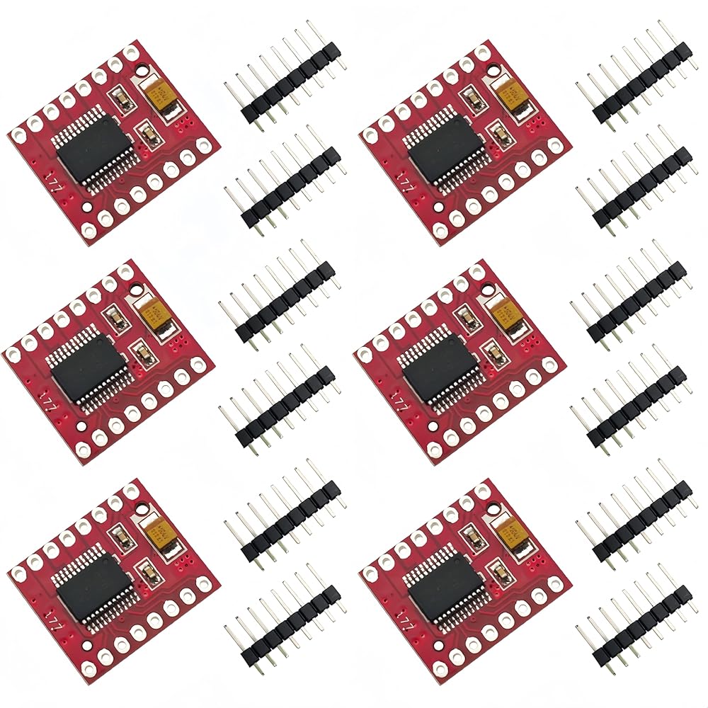
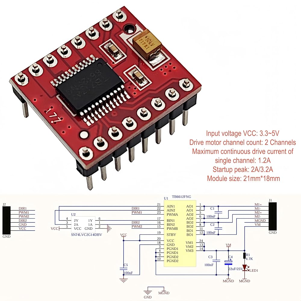
This TB6612FNG module has significantly improved efficiency and reduced size.
Please note that positive and negative (wire connection), recommended input voltage for TB6612FNG module is 12V or below.
TB6612FNG is a dual channel DC motor driver chip. It adopts an H-bridge design and can independently drive two DC motors or one stepper motor, suitable for projects such as robots and small intelligent vehicles.
This chip supports forward and reverse rotation, braking, and standby functions, with specific features of high efficiency and low power consumption. Can provide MAX with a continuous current of 1.2A per channel and a peak current of up to 3.2A.
The working voltage range is wide, and it integrates overheating and undervoltage protection, which is widely used in embedded control systems.
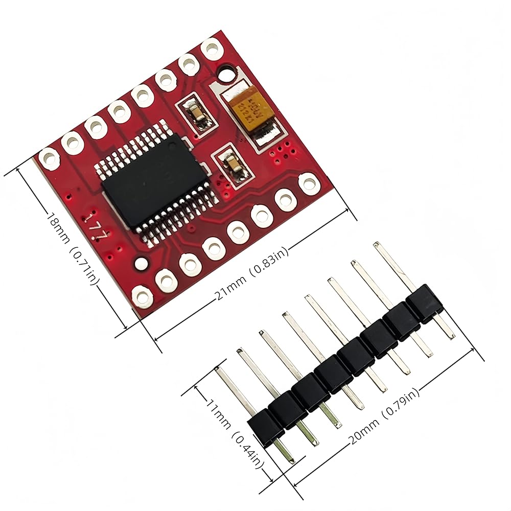
Size is 21*18mm, weight is 3g, color is red board
Drive voltage: YM input 4.5-10V
Logic level: VCC input 2.7-5.5V
Working current: 1.2A, peak current: 3.2A
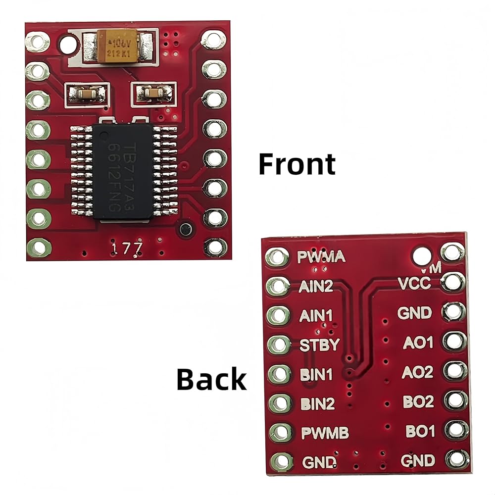
Pin Description:
AINI/AIN2, BIN1/BIN2, PWMA/PWMB: control signal input terminals
AO1/A02, BO1/B02: two motor control output terminals
STBY: control pin for normal working/standby mode
VM ( VCC (2.7~5.5V): logic level input terminals
GND: ground
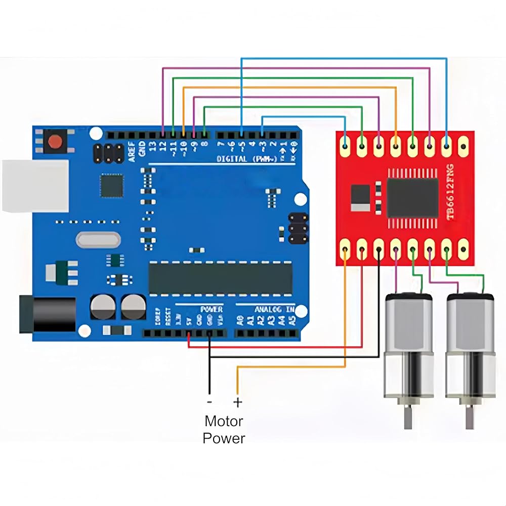
Usage of TB6612:
TB6612 is dual drive, which means it can drive two motors.
The following are the IO ports for controlling two motors.
The STBY port is connected to the IO port of the microcontroller, and all motors are reset to stop.
Setting 1 controls the forward and reverse rotation through AIN1, AIN2, BIN1, and BIN2
VM connected to power supply within 12V
VCC connected to 5V power supply
GND connected to ground
Drive 1 way
PWMA connected to the PWM port of the microcontroller
Truth table:
AIN1 0 0 1
AIN2 0 1 0
Stop, forward and reverse
A01
AO2 is connected to the two pins of motor 1
Drive 2 channels
PWMB connected to the PWM port of the microcontroller
Truth table:
BIN1 0 0 1
BIN2 0 1 0
Stop, forward and reverse
B01
Connect the two pins of BO2 to motor 2
 6 قطعة مفتاح ريد اتصال ريد مفتوح عادة (N/O) مفتاح الحث المغناطيسي (2 مللي متر * 14 مللي متر) ، مفتاح ريد ياباني أصلي KOFU OKI
KWD 3
6 قطعة مفتاح ريد اتصال ريد مفتوح عادة (N/O) مفتاح الحث المغناطيسي (2 مللي متر * 14 مللي متر) ، مفتاح ريد ياباني أصلي KOFU OKI
KWD 3
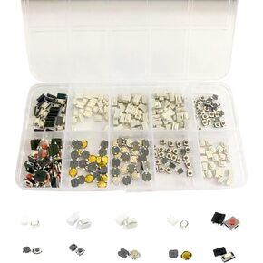 طقم مفاتيح ميكرو 250 قطعة بزر ضغط لحظي - لمعدات الصوت التلفزيونية ومسجلات الفيديو والكاميرات وألعاب الكمبيوتر وغيرها من الأجهزة المنزلية
KWD 4.500
طقم مفاتيح ميكرو 250 قطعة بزر ضغط لحظي - لمعدات الصوت التلفزيونية ومسجلات الفيديو والكاميرات وألعاب الكمبيوتر وغيرها من الأجهزة المنزلية
KWD 4.500
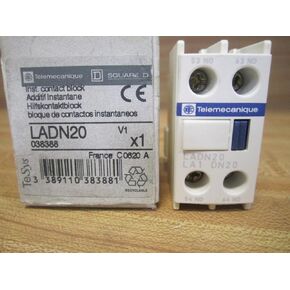 Telemecanique LADN20 جهة الاتصال المساعدة LA1DN20 038388
KWD 9.500
Telemecanique LADN20 جهة الاتصال المساعدة LA1DN20 038388
KWD 9.500
 -24%
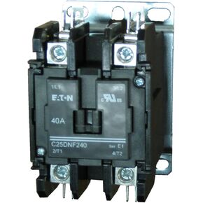
موصل إيتون C-H 2P، C25DNF240B
KWD 25.500
-24%
موصل إيتون C-H 2P، C25DNF240B
KWD 25.500