- التسوق ، اصبح سهلا.
- /
- احصل على التطبيق!
100% brand new and high quality
Circuit Principle:
4.Input circuit is composed of J1, R5, R6 and C3. When the current of measured circuit passes through R5,it will generate a voltage on R5. This voltage will be input to chip 31-pin through R6 current limiting and be processed, C3 is input voltage filtering capacitor.
5.Display circuit is composed of DS1-DS4, D1, D4, 4 digital tubes can be drived directly by the chip. R10 is current limiting resistance of DS1-DS3 digital tubes decimal points.
Finished Product Debugging:
1.After connecting with DC 5V (please notice the polarity),the digital tube will display -.000 or .000,this is normal.
2.Use multimeter to measure the voltage between chip 36-pin and 35-pin,and adjust VR1 potentiometer let it be 100mV.
Key Points Voltage Reference Value:
1.Chip 1-pin and 21-pin: 5V.
2.Chip 36-pin and 21-pin: 100mV,
3.Chip 26-pin and 21-pin: -5V.
Specification:
Material: PCB + Metal + Plastic
Type: Digital Ammeter Kit
Panel Size:79 x 44mm / 3.11 x 1.73in
Mount Size:71 x 39mm / 2.8 x 1.53in
Quantity: 1 Pc
Electricity Parameters:
Working Voltage: DC 5V
Working Current: 35 mA
Accuracy: ±1mA
Measuring Range: 0 - 2A
Over Range Indication: Primacy Display 1/-1
Display Color: Red
Quantity: 1Set
Package includes:
1Set x Digital Ammeter Kit
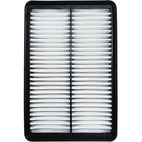 FDPAF99096 فلتر هواء المحرك لتوكسون (2023-2022)، سانتا في (2023-2021)، سوناتا (2023-2020)، سانتا كروز (2023-2022)، K5 (2023-2021)، كرنفال (2023-2022)، سورينتو 2.5 لتر (23-21)، سبورتاج 2.5 لتر (2023)
KWD 7
FDPAF99096 فلتر هواء المحرك لتوكسون (2023-2022)، سانتا في (2023-2021)، سوناتا (2023-2020)، سانتا كروز (2023-2022)، K5 (2023-2021)، كرنفال (2023-2022)، سورينتو 2.5 لتر (23-21)، سبورتاج 2.5 لتر (2023)
KWD 7
 مجموعة حشية غطاء صمام المحرك من Ortopia 12030-P8A-A00 VS50576R متوافقة مع 1998-2004 Honda Accord Odyssey Pilot، 1997-2003 Acura CL TL MDX 3.0L 3.2L 3.5L V6 SOHC J30A J32A J35A
KWD 11.500
مجموعة حشية غطاء صمام المحرك من Ortopia 12030-P8A-A00 VS50576R متوافقة مع 1998-2004 Honda Accord Odyssey Pilot، 1997-2003 Acura CL TL MDX 3.0L 3.2L 3.5L V6 SOHC J30A J32A J35A
KWD 11.500
 زوج واحد من مروحة تبريد المبرد AC من الجانب الأيسر والأيمن 7+5 شفرات متوافقة مع 2012-2015 Honda Civic، 2013-2017 A-cura ILX 1.5L 2.0L 2.4L
KWD 40
زوج واحد من مروحة تبريد المبرد AC من الجانب الأيسر والأيمن 7+5 شفرات متوافقة مع 2012-2015 Honda Civic، 2013-2017 A-cura ILX 1.5L 2.0L 2.4L
KWD 40
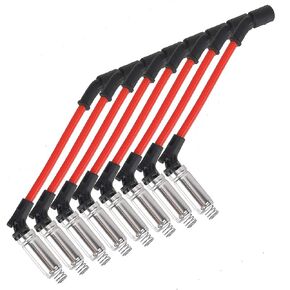 مجموعة أسلاك توصيل الإشعال 10.2 مم، كابل الإشعال من السيليكون، نهايات التمهيد من السيليكون مناسبة لجنرال موتورز سوبربان كورفيت سيلفرادو 1500-2500 99-06 LS1 VORTEC 4.8L 5.3L 6L V8 48322R 48322 (أحمر)
KWD 11
مجموعة أسلاك توصيل الإشعال 10.2 مم، كابل الإشعال من السيليكون، نهايات التمهيد من السيليكون مناسبة لجنرال موتورز سوبربان كورفيت سيلفرادو 1500-2500 99-06 LS1 VORTEC 4.8L 5.3L 6L V8 48322R 48322 (أحمر)
KWD 11


