- التسوق ، اصبح سهلا.
- /
- احصل على التطبيق!
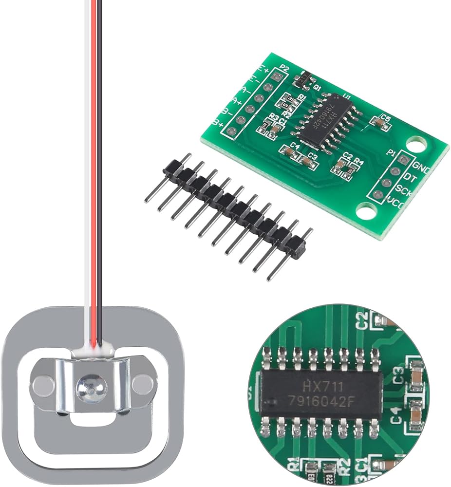
Load cell is an instrument that helps to determine size of a load (either a force or weight) and converts mechanical force into digital output.
It consists of a metal core and a set of electrical resistances that transform when a force is applied to it. But it returns to its original state after force removed.
It have many purposes, use a load cell, need calibrate it can increase or decrease calibration factor units to get correct weight using a microcontroller.
The sensor have 3 ways to use it:
1. Using a Single Load Cell 1x50kg by Adding 2 Resistors
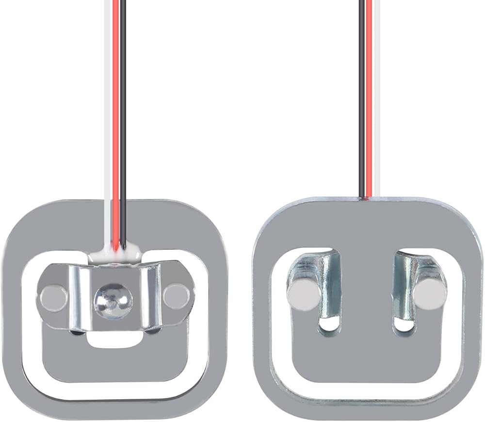
Connect outer wire(white and black) of load cell to E+ and E- outputs of hx711 module.
Connect middle cable(red) of load cell to A+ input of hx711 module. Connect two 1k resistors to A- input of hx711 module. Then the other end of resistor to white and black wires.
Connect GND of hx711 module to board GND, and VCC to board 5V pin.
Connect DT and SCK of hx711 module to any digital IO pins of board.
2. Using Two Load Cells in a Singel Circuit 2x50kg (100kg)
Connect opposite sides of outer wires(white and black) of two load cells.
Connect outer wire pairs to E+ and E- output of hx711 module.
Connect middle wire(red) of load cell to A+ and A- inputs of hx711 module.
Connect GND of hx711 module to board GND, and VCC to board 5V pin.
Connect DT and SCK of hx711 module to any digital IO pins of board.
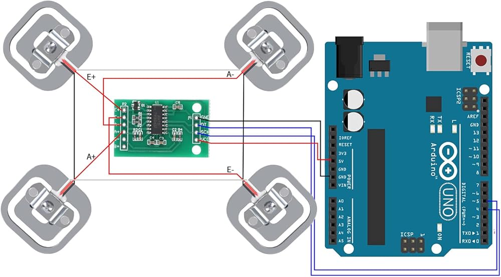
3. Using 4 Load Cells in a Single circuit 4x50kg (200kg)
Form a loop by linking same color outer wires(white and black) of the four load cells.
Connect middle cable(red) of one of the diagonals to the E+ and E- outputs of the HX711 module.
Connect the other diagonal to the A+ and A- inputs of the HX711 module.
Connect GND and hx711 module to board GND, and VCC to board 5V pin.
Connect DT and SCK of hx711 module to any digital IO pins of board.
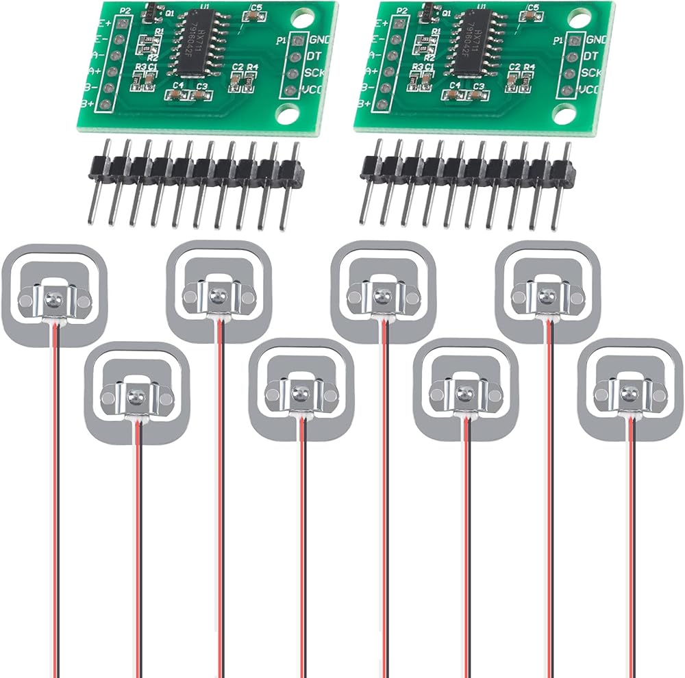
Package included:
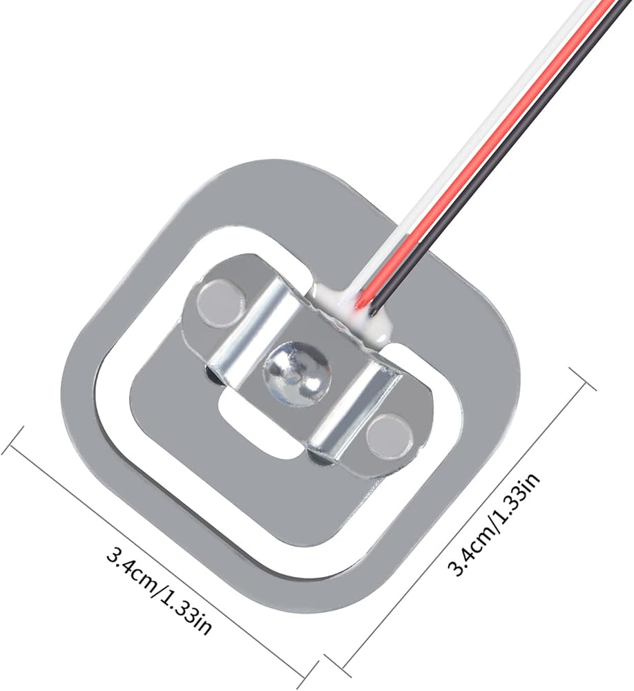
8 x 50kg half-bridge load cell
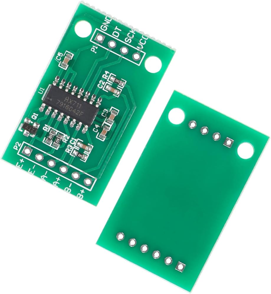
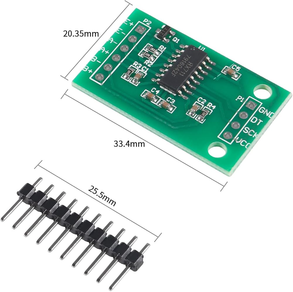
2 x HX711 AD weight module
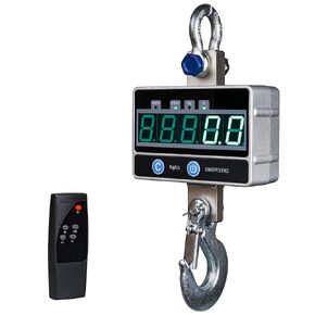 مقياس الرافعة الرقمي 2000 كجم / 4400 رطل 2 طن مع جهاز تحكم عن بعد، ميزان معلق إلكتروني صناعي ثقيل، شاشة LED
KWD 30
مقياس الرافعة الرقمي 2000 كجم / 4400 رطل 2 طن مع جهاز تحكم عن بعد، ميزان معلق إلكتروني صناعي ثقيل، شاشة LED
KWD 30
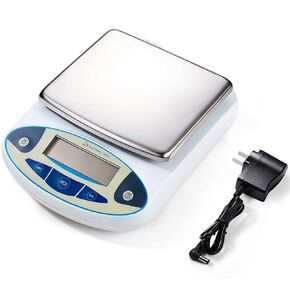 ميزان مختبر 5000 جرام × 0.01 جرام، دقة عالية، ميزان تحليلي إلكتروني، ميزان دقيق للمختبر، ميزان رقمي للمطبخ، ميزان مجوهرات، مقياس علمي، سطح وزن 6.7 بوصة Dp
KWD 30.500
ميزان مختبر 5000 جرام × 0.01 جرام، دقة عالية، ميزان تحليلي إلكتروني، ميزان دقيق للمختبر، ميزان رقمي للمطبخ، ميزان مجوهرات، مقياس علمي، سطح وزن 6.7 بوصة Dp
KWD 30.500
 مقياس دينامومتر، مقياس 10N نيوتن متر، جهاز عمل ميكانيكي مع تصميم هيكل قياسي
KWD 3.500
مقياس دينامومتر، مقياس 10N نيوتن متر، جهاز عمل ميكانيكي مع تصميم هيكل قياسي
KWD 3.500
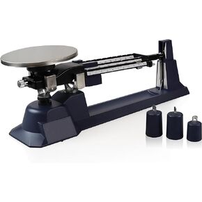 ميزان باركو ساينتيفيك PA0070 ثلاثي الشعاع، سعة 610 جرام
KWD 51.500
ميزان باركو ساينتيفيك PA0070 ثلاثي الشعاع، سعة 610 جرام
KWD 51.500