- Shopping, made easy.
- /
- Get the app!
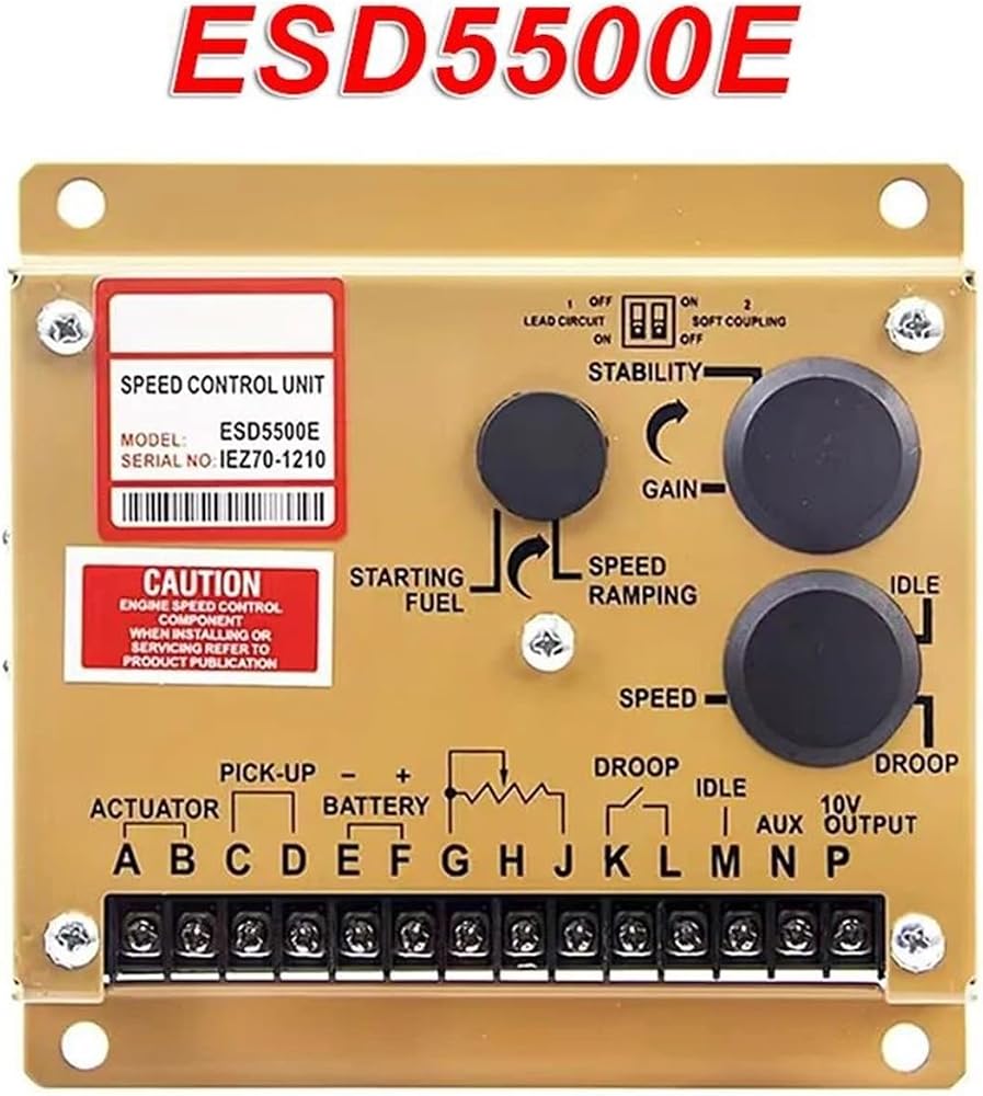
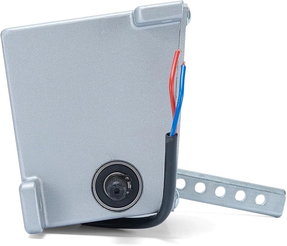
Speed Controller
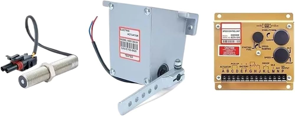
The ESD5500E Series speed control unit is an all electronic device designed to control engine speed with fast and precise
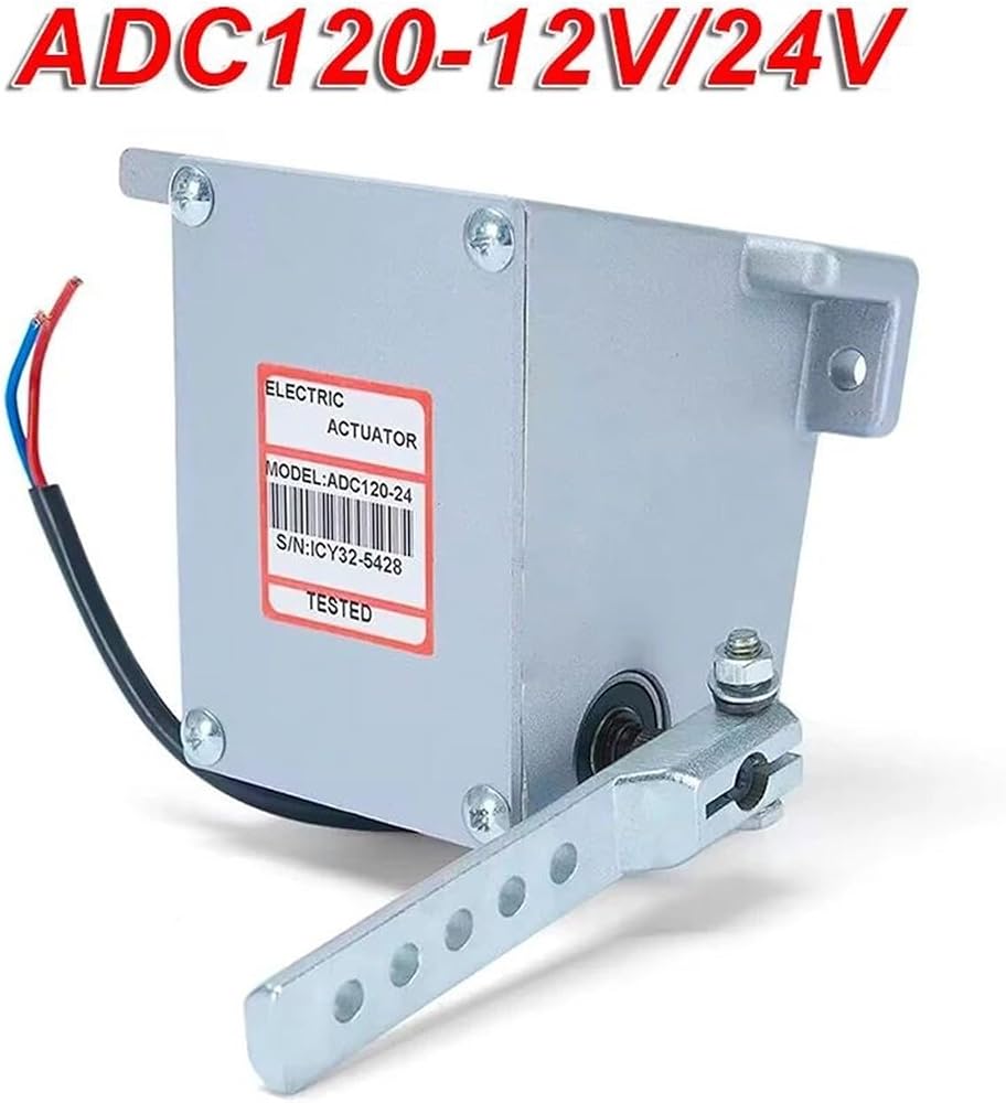
response to transient load changes. This closed loop control,when connected to a proportional electric actuator and supplied with a magnetic speed sensor signal, will control a wide variety of engines in an isochronous or droop mode. It is
designed for high reliability and built ruggedly to withstand the engine environment.
Simplicity of installation and adjustment was foremost in the design. Non-interacting performance controls allow near opti
mum response to be easily obtained.
The primary features of the ESD5500E Series speed control unit are the engine STARTING FUEL and SPEED RAMPING
adjustments. The use of these features will minimize engine exhaust smoke experienced prior to attaining engine operating speed. Other features include adjustable droop and idle operation, inputs for accessories used in multi-engine or special applications, protection against reverse battery voltage, transient voltages, accidental short circuit of the actuator and fail safe design in the event of loss of speed sensor signal or battery supply.
The ESD5500E Series speed control unit is compatible with all proportional actuators except the ACB2000 electric actuator. When the ESD5500E Series speed control unit is used with a ADC100 Series electric actuator, the DROOP adjustment range will be less due to this actuator's low current demand.
DESCRIPTION
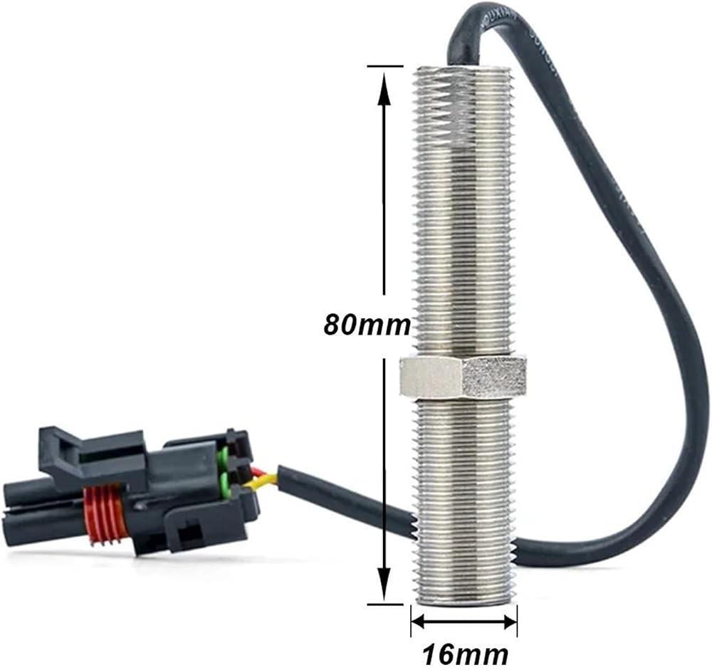
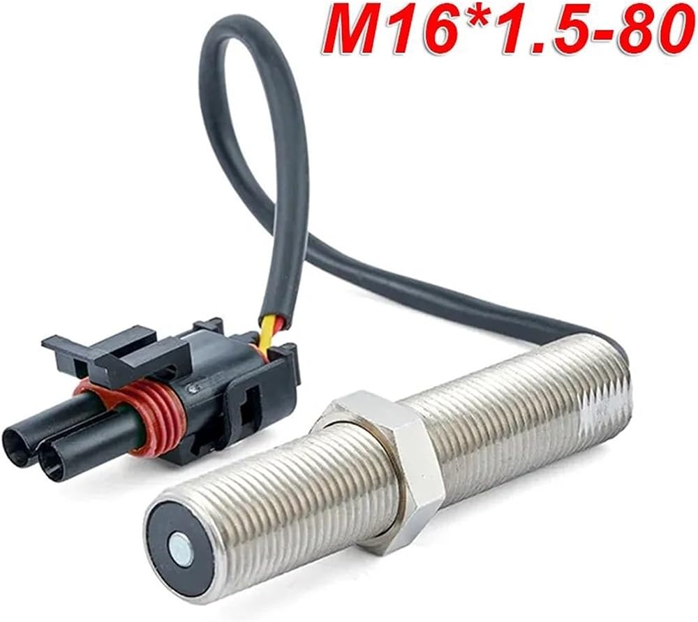
Engine speed information for the speed control unit is usually received from a magnetic speed sensor. Any other signal generating device may be used provided the generated frequency is proportional to engine speed and meets the voltage
input and frequency range specification. The speed sensor is typically mounted in close proximity to an engine driven ferrous gear, usually the engine ring gear. As the teeth of the gear pass the magnetic sensor, a signal is generated which is proportional to engine speed.
Signal strength must be within the range of the input amplifier.
An amplitude of 0.5 to 120 volts RMS is required to allow the unit to function within its design specifications. The speed signal is applied to Terminals C and D of the speed control unit.
Between these terminals there is an input impedance of over 33,000 ohms. Terminal D is internally connected to Terminal E, battery negative. Only one end of the shielded cable should be connected.
When a speed sensor signal is received by the controller, the signal is amplified and shaped by an internal circuit to provide an analog speed signal. If the speed sensor monitor does not detect a speed sensor signal, the output circuit of the speed control unit will turn off all current to the actuator.
 DP-301-1 DC310V 30W 30001r/min Drain Pump Motor for Dish Washer G1 S1 Dishwasher Parts
KWD 38.500
DP-301-1 DC310V 30W 30001r/min Drain Pump Motor for Dish Washer G1 S1 Dishwasher Parts
KWD 38.500
 1Pcs PX-3-1 AC220-240V 50Hz 13W Drain Pump Motor for Clothes Dryer Drying Machine Parts
KWD 35.500
1Pcs PX-3-1 AC220-240V 50Hz 13W Drain Pump Motor for Clothes Dryer Drying Machine Parts
KWD 35.500
 1Pcs EAU63743803 26V 1.7A 45W NTWC021S03 Drain Pump Motor for Washing Machine Washer Drainage Parts
KWD 33.500
1Pcs EAU63743803 26V 1.7A 45W NTWC021S03 Drain Pump Motor for Washing Machine Washer Drainage Parts
KWD 33.500
 1Pcs YXW30-2A(L) Aluminum Coil 220-240V 50/60Hz 60w 0.25A Dishwasher Circulating Pump
KWD 85.500
1Pcs YXW30-2A(L) Aluminum Coil 220-240V 50/60Hz 60w 0.25A Dishwasher Circulating Pump
KWD 85.500